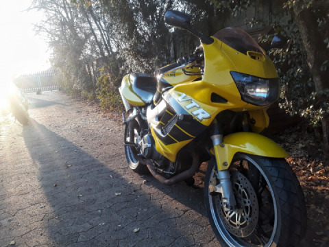
VTR Valve Clearance
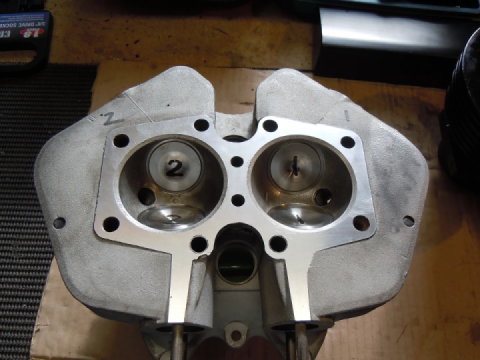
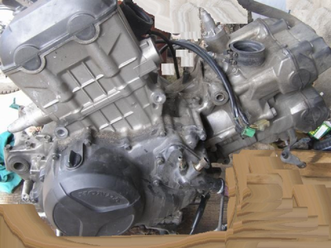
There are 4 valves per cylinder. You can see by the placement of the carburetor that the side closest to the carbs are the intake. The side of the cylinder where the exhaust pipes exits are the exhaust.
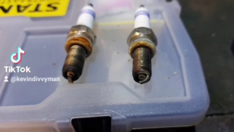
On cold engine, measure distance between valve lifter and cam lobe at TDC. Better to have near the loose (max) side. As the valve seat wear, the valve clearance will tighten up. Out of range, you will need to remove cam shafts to install different shims.
Intake (0.16 mm) Min (mm) 0.13 Max (mm) mm 0.19
Exhaust (0.31 mm) Min (mm) 0.28 mm Max (mm) 0.34
If you are measuring a less than the minimum clearance, you will need to take out the old shim and put in a new shim that thinner. That will give you more clearance between the shim and the cam.
Shims can be sourced locally from a variety of sources. Any older motorcycle service shop should have a big box of various types of shims. Some Yamaha, Ford and other makers use shims that will fit.
Starting with the Rear Cylinder
The rear cylinder is at Top Dead Centre (TDC) on the Compression stroke.
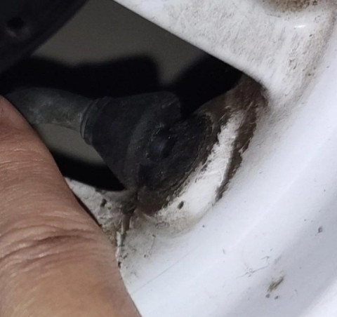
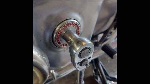
1. With a 17mm socket, turn the crankshaft end bolt (behind centre cap mounted on the generator cover) in an anti-clockwise direction only until the RT mark lines (behind inspection cap) becomes visible. You need to look straight on at eye level through the inspection hole and you will see the alignment mark just under the T. You may find a torch comes in useful to shine in the hole as it's not always visible.
RT – When this mark is visible, it means the Rear cylinder is at Top Dead Centre in it’s stroke. TDC can occurs twice, once during the compression stroke and during the exhaust stroke. The direction the cams are pointing determines which stroke,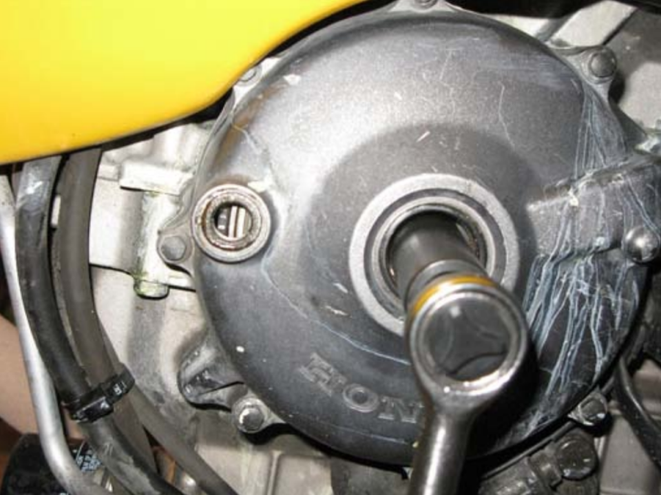
RT alignment mark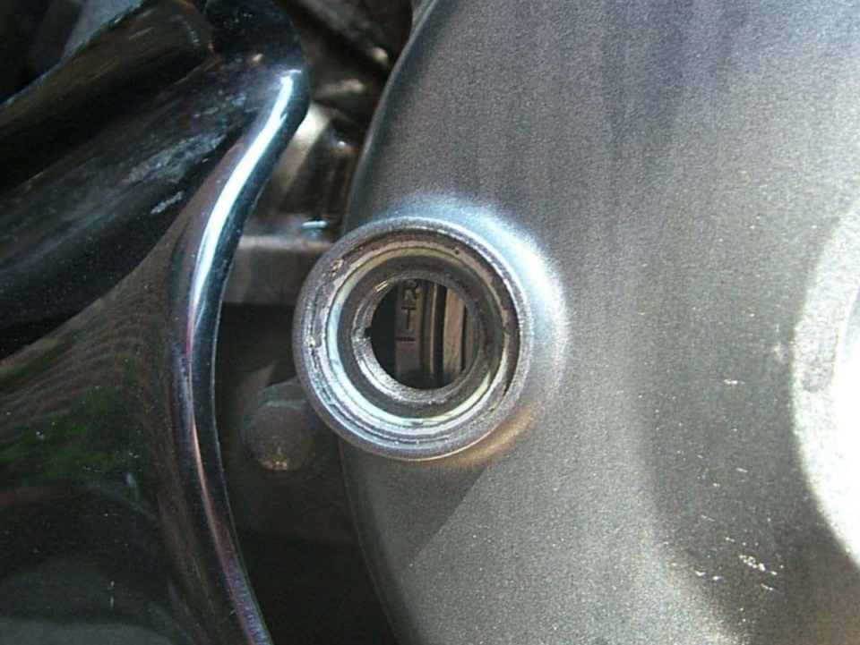
2. You now have to verify whether or not you are on the compression stroke as the RT lines up on other strokes. To do this, look at the cam lobe positions and they should be pointing upwards and inwards. If they are not, turn the crankshaft in an anti-clockwise direction 360 degrees until the RT alignment mark comes around again, the positions of the cam lobes should now be pointing upwards and inwards.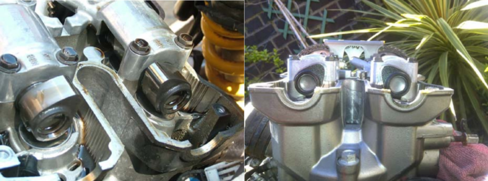
Cam lobes must be pointing inwards on the rear cylinder at TDC (compression)
3. With the crankshaft on RT and cam lobes pointing upwards and inwards it's time to check the camshafts are at exact alignment by looking at the alignment marks on each cam sprocket. This would be essential if you have had a previous CCT failure as it's likely that the chain has jumped some teeth. You will see an RI (rear intake) and RE (rear exhaust) with a horizontal line on each sprocket and these should align on the outside edge horizontal with the top of the cylinder head.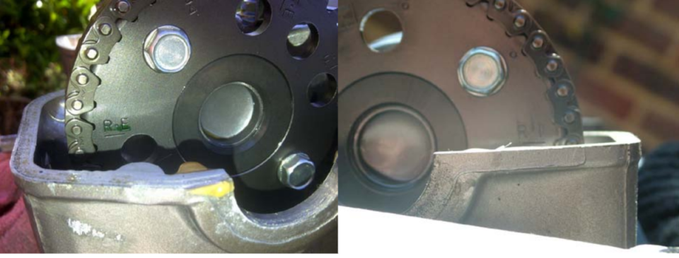
Note: Checking the valve clearance when the piston is not at TDC will result in wrong readings.
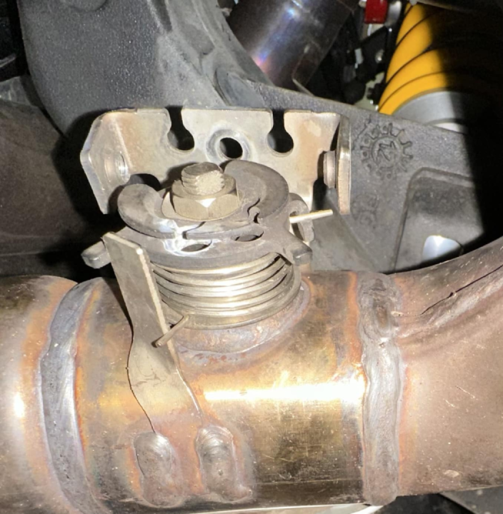
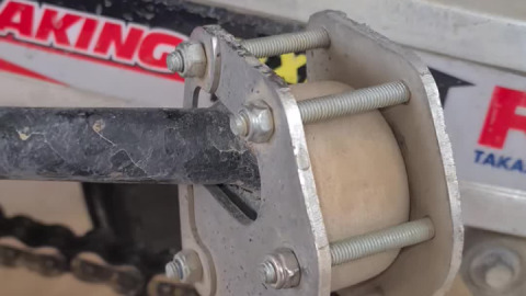
You can also check the cam chain tension at this time. You now want to tighten the threaded part of the tensioner down until you have between 5 - 7mm of up and down play from the outside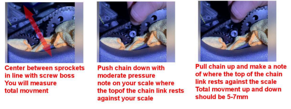
edge of the cam chain between the two cam sprockets. It's a similar process to tightening the slack in your drive chain. It is preferred to be on the slack side as it's going to put less stress and strain on engine components than if it's overtightened.
Try to tighten the tensioner just using your thumb and finger to get a feel of the tension you are able to apply on the cam chain. By doing this test, if you notice some noise from the cam chain in the future; you can do a quick adjustment without a disassembly. My result: Thumb and finger tight resulted in 5 mm tension. Back off ¼ turn and the tension was 6 mm.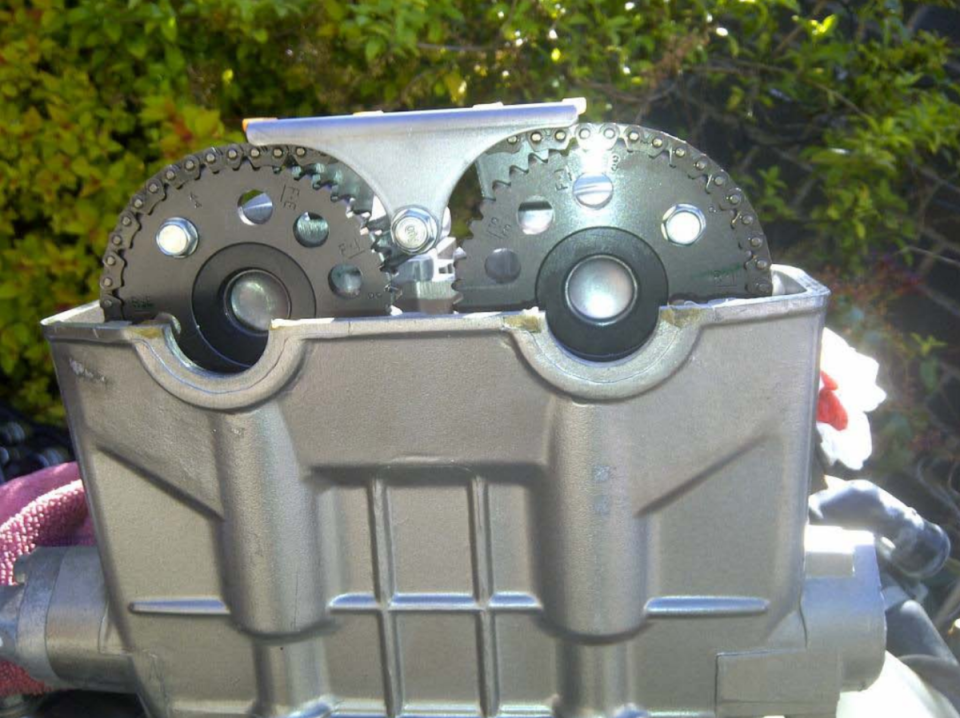
For the Front Cylinder
The front cylinder is pretty much the same procedure as the rear except the timing now has to be repositioned on FT for Front Top Dead Centre on the compression stroke and the camshaft lobes will be the reverse from the rear. Rear lobes need to be pointing upwards and away from each other.
1. Once again using the 17mm socket on the crankshaft end bolt through where the centre cap was on the generator cover, turn the crankshaft in an anti-clockwise direction only, 450 degrees
(one and quarter turns) until the FT lines up with the alignment marks through the inspection window. You will find the FT comes around once and then on the second time you see it you would have turned it 450 degrees and be on the compression stroke. You will also find the FT would have turned it 450 degrees and be on the compression stroke. You will also find the FT comes around directly after an F mark, be careful to stop on the right one. If you miss the mark, then go around again always turning in an anti-clockwise direction until it comes back around.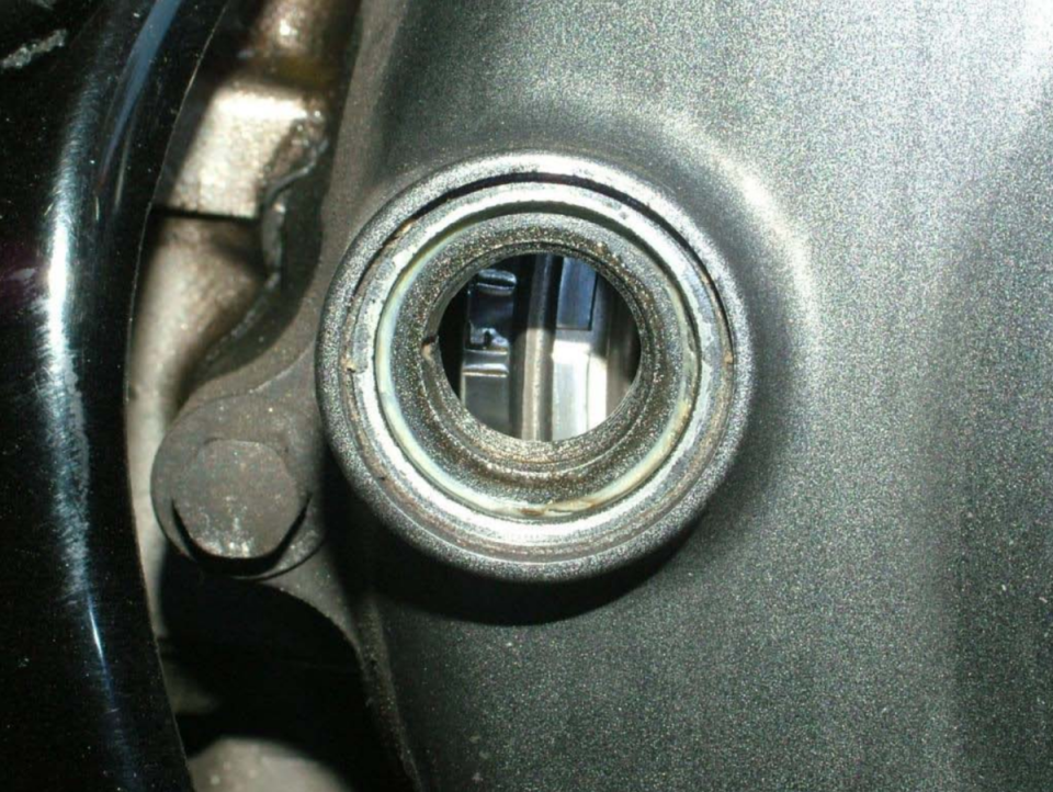
2. Check the positions of the cam lobes and if you are on the compression stroke then they will be pointing upwards and away from each other. If not, then you will have to keep turning until the FT comes around again and the alignment marks line up. You should now be at Top Dead Centre on the compression stroke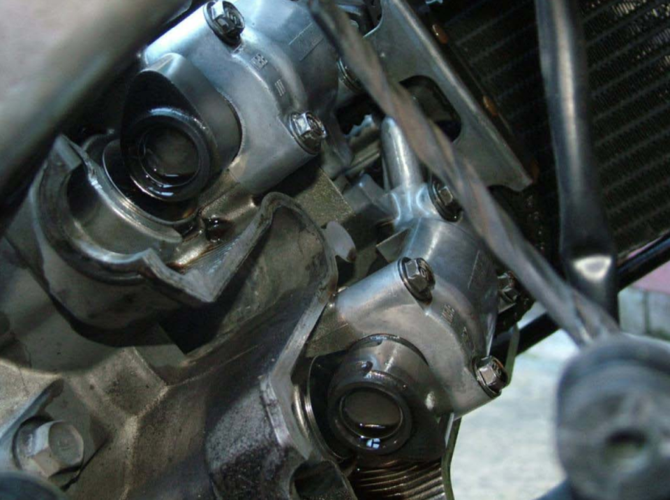
Front cam lobes point outward in TDC (compression)
3. Once you are happy that all alignment marks line up, you can then check the markings on the end of the cam sprockets as you did with the rear. The only difference is that instead of RI and RE they will be FI (Front Intake) and FE (Front Exhaust). These should align on the outside edge horizontally against the top of the cylinder head.
Check your valve clearance and check your cam chain tension. You can record your results on the attached spreadsheet. There is a section on the lower part of the spreadsheet to help choose the right shim size.

 Follow
1.8K
Follow
1.8K