Part 2 - Kawasaki Wiring Harness Connector Identification Guide
Throttle Position Sensor 
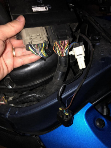
Certainly the most problematic engine sensor associated with the Kawasaki electronics, the Throttle Position Sensor is located on the right side of the Throttle Bodies and just above the intake boots on the engine. Because the sensor is tucked away almost underneath the right side of the throttle bodies, it becomes very easy to overlook when hooking up electrical connectors. The sensor wiring exits the harness on a 6inch pigtail into a white, triangular shaped connector. Its mating connector, also white in color, extends the 3 wires to a flat, black connector which will connect to the Throttle Position Sensor. Power Commander 3 models will display similar white connectors which connect to the ones pictured above.
Lower Fuel Injector Connectors 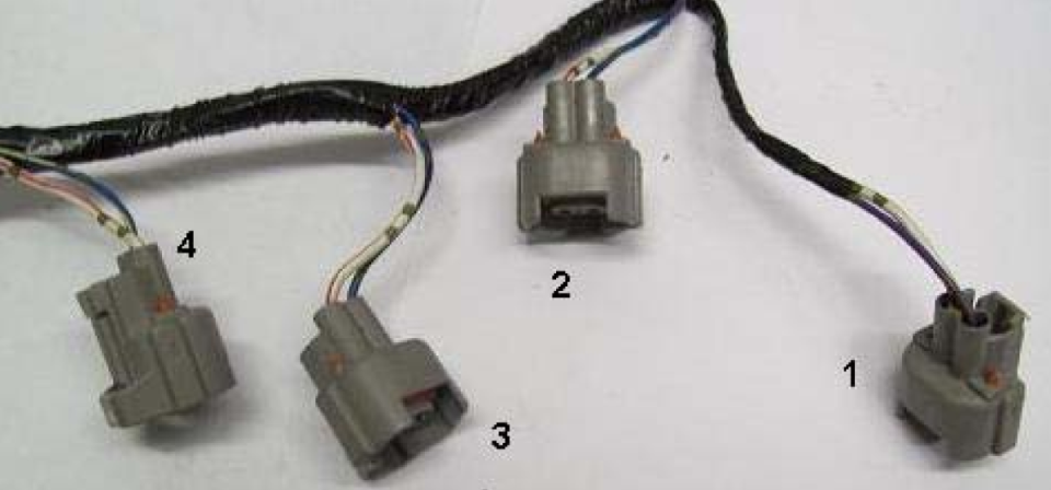
These 4 connectors extend on their own leg from the main wiring harness and connect to the small, black and oval connectors on the Power Commander. The 4 remaining connectors on the Power Commander plug directly onto the lower fuel injectors. In other words, the Power Commander will connect between the main wiring harness connectors pictured above and the fuel injectors. This information is only true when using a Hyper FIT Methanol Fuel Injection Conversion.
Engine Coolant Temperature Connector 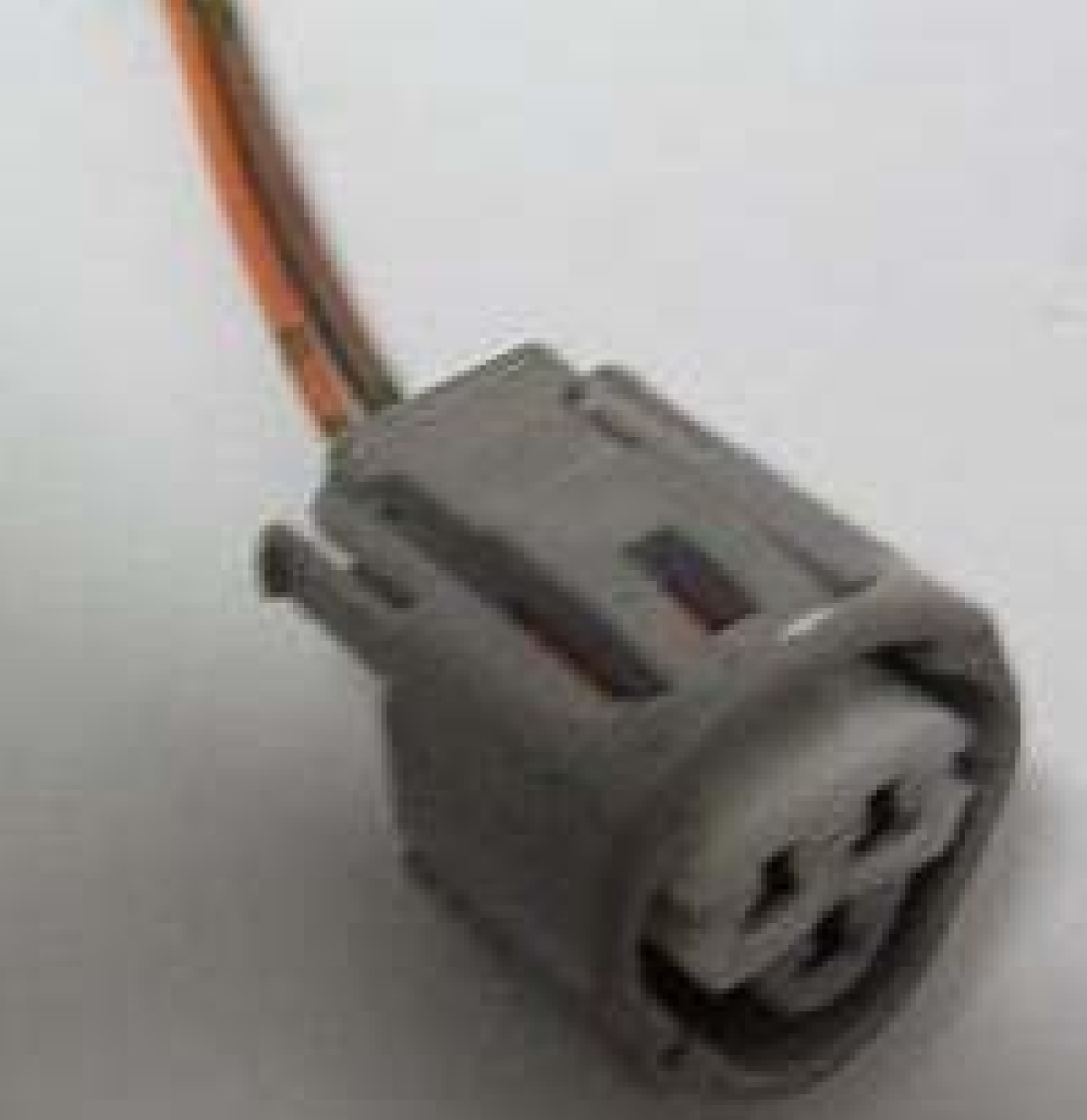
An extension to the lower fuel injector harness, this sensor relays vital information about the engines operating temperature back to the ECU. The Engine Coolant Temperature Sensor is located just below the #1&2 fuel injectors. When using a Power Commander 5 or Auto Tune Module, the orange wire contained in this connector is needed for its operation as well.
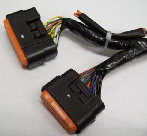
Ignition Coils & Air Pressure Sensor Connectors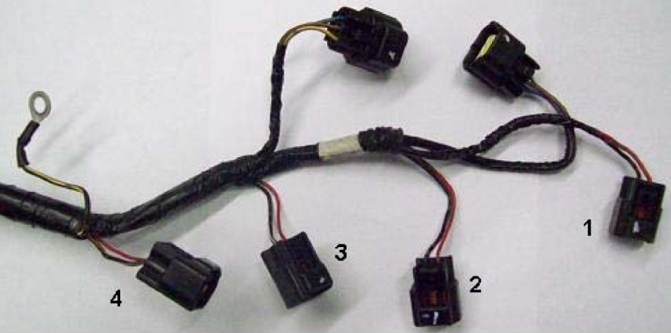
The (4) two wire connectors in the photo above connect to the ignition coils of the engine. The connector farthest from the ECU is designated for the #1 cylinder. The other cylinders descend sequentially. The Intake Air Pressure and Barometric Pressure Sensor Connectors also extend from this same harness leg. The pressure sensors are located on the front of the throttle bodies. The Intake Air Pressure Sensor must be connected to a vacuum hose leading to the throttle bodies. The Barometric Pressure Sensor should remain open to the atmosphere. These sensors may be interchanged, they are also identical in appearance and construction and are very rarely the source of a problem.
A small black wire with a yellow stripe will be observed exiting the harness near the #4 coil connector. This wire should be connected to the grounding post on top of the valve cover. This is not a suitable grounding location for any other component. The purpose of this wire is to absorb any RFI voltage flowing throughout the valve cover, preventing the coils from firing at undesired intervals.
Camshaft Position Sensor Connector 
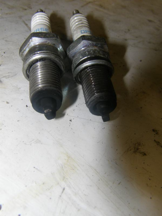
The Connector for the Camshaft Position Sensor Connector extends from the harness just before the connectors for the Ignition Coils. Located on the front of the engine, just below the valve cover and above the exhaust ports, the Camshaft Position Sensor works in conjunction with the Crank Sensor to provide the vital first ignition cycle to the engines spark plugs. After the engine is running, the Camshaft Position Sensor serves little purpose but its proper operation is required upon every startup.
Upper Fuel Injector Connectors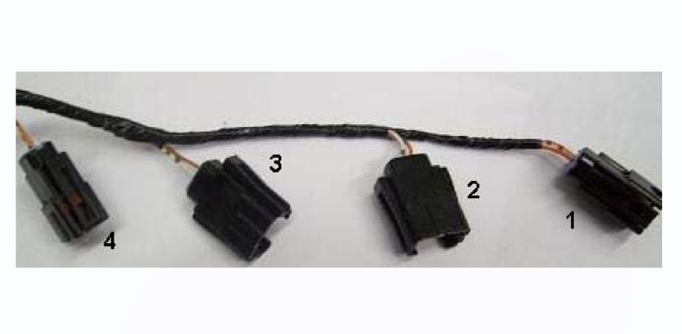
The Upper Fuel Injector Connectors plug into the Fuel Injectors located on top of the airbox. These connectors must be changed from stock form to accept our Methanol injectors. The connector at the end of the line, farthest from the ECU is for cylinder #1.
Intake Air Temperature Sensor 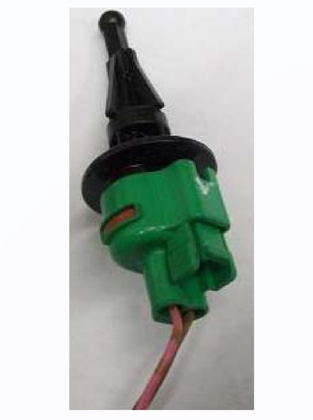
Its unique shape and color make the Intake Air Temperature Sensor one of the more recognizable components on the 05-06 ZX6R wiring harness. Some injection designs use a rubber grommet inside the airbox to locate the sensor. This sensor needs to be exposed to the air charge entering the airbox. I have found that fastening the sensor to the upper injector wiring harness is sufficient for its proper operation.
Secondary Throttle Valve Actuator & Sensor 
This view from the right side (inside) of the Throttle Bodies shows the STVA & Sensor in factory configuration. These components control the Secondary set of throttle plates housed within the throttle body bores. The primary function of this system is to control intake air velocity and intake noise. After experiencing numerous failures to these components Hyper FIT began removing the actuator and sensor along with the secondary throttle plates. As a result, I have enjoyed an increase of reliability with no sacrifice to power output or throttle response.
Secondary Throttle Valve Actuator Connector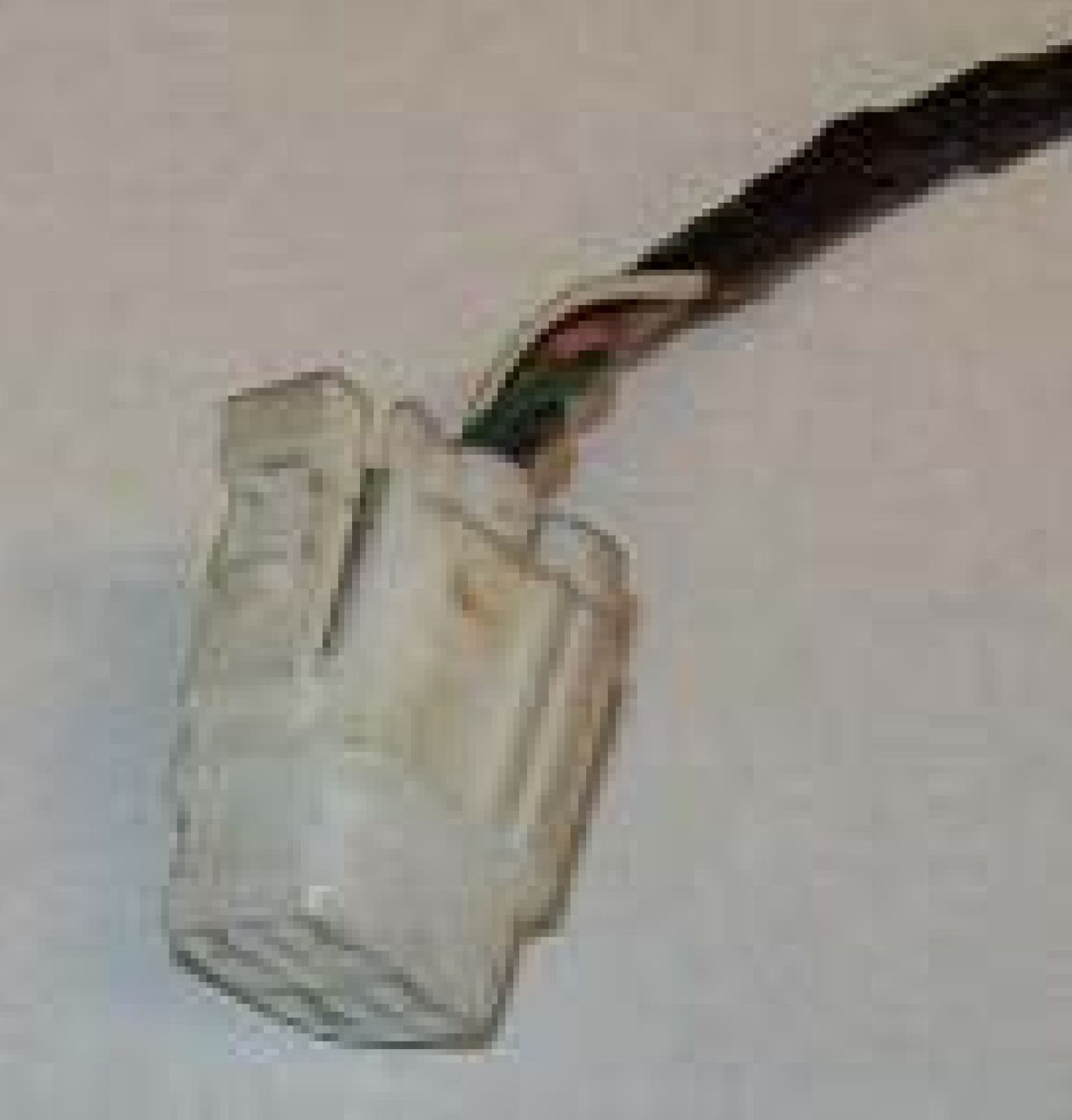
Any set of Throttle Bodies retaining the STVA Sensor and Actuator will require the connector displayed above to operate correctly. Another, more preferred option would be to remove the Actuator, Sensor and Secondary Throttle Valves.
Secondary Throttle Valve Sensor Connector 
Any set of Throttle Bodies retaining the STVA Sensor and Actuator will require the connector displayed above to operate correctly. Another, more preferred option would be to remove the Actuator, Sensor and Secondary Throttle Valves.
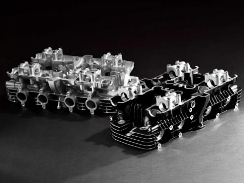
*Secondary Throttle Valve Actuator & Sensor Removed*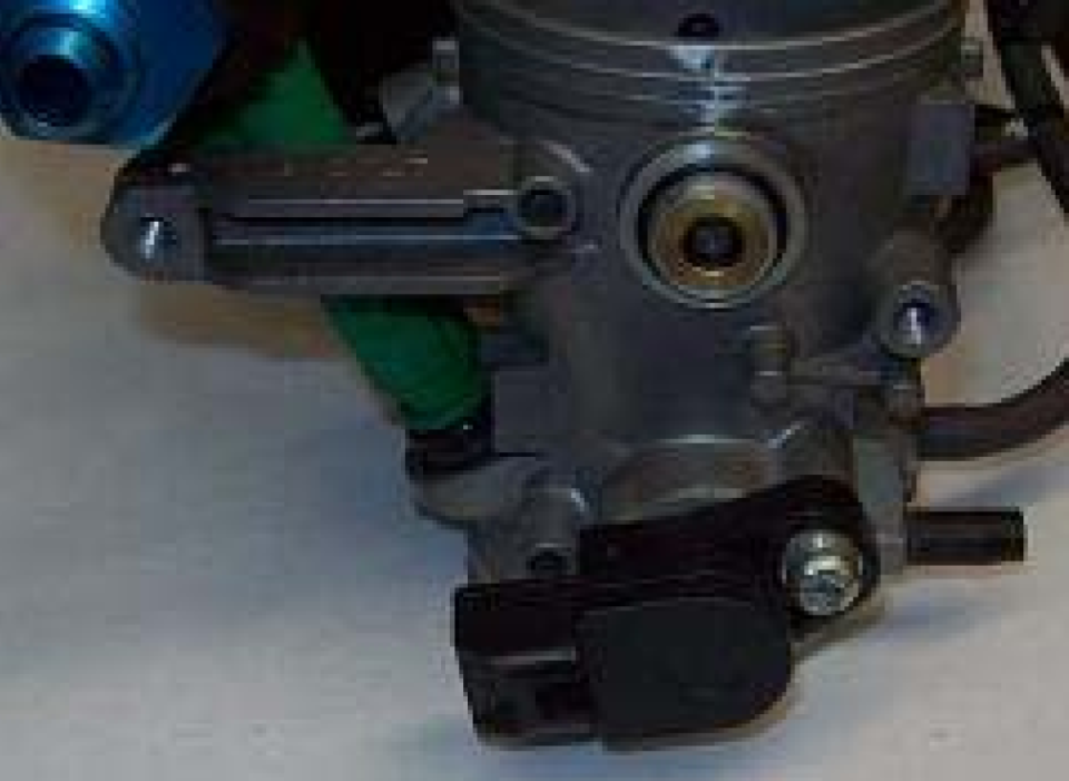
This photo shows a set of throttle bodies with the STVA removed.

 Follow
3.4K
Follow
3.4K