Wiring
Started to look at the wiring harness a week or so ago.
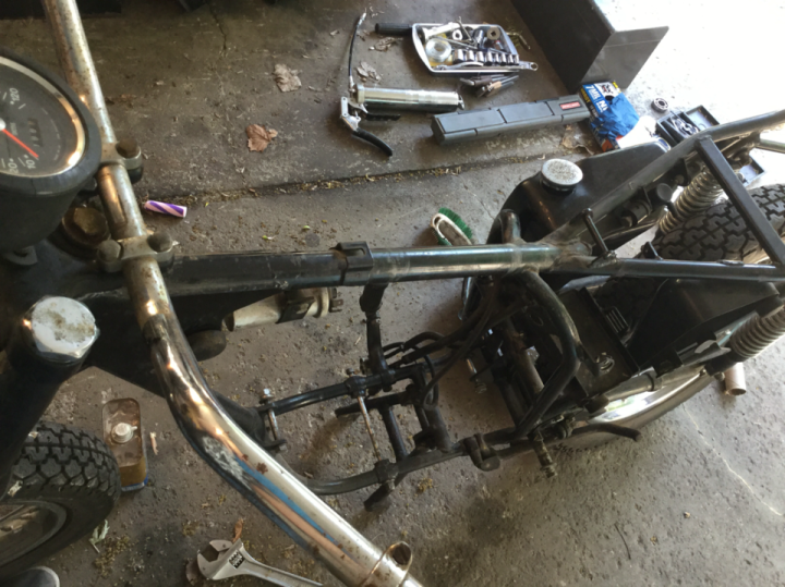
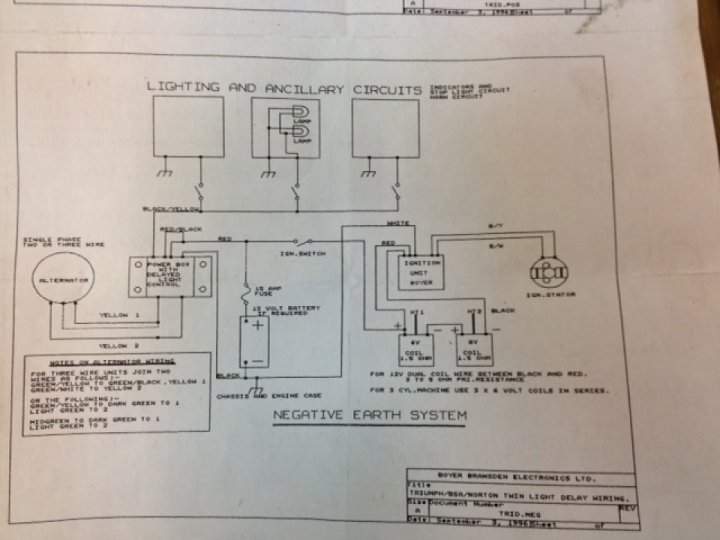
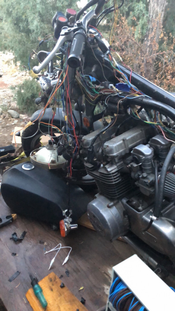
The wiring on this bike consists of two main wiring harnesses. One connects to the stuff in the headlight shell as well as the front turn signals, zener diode voltage regulator, ignition switch, front brake switch, and oil pressure switch. The other harness provides connection to the brake and tail lights, rear turn signals, rear brake switch, charging components (alternator, rectifier, and battery), ignition components (coils, points, and condensers), and the horn and flasher unit. There is also a cable from each of the handlebar switch housings, and some simple two-conductor cables for the instrument lamps and the ignition points. All of the cables and harnesses interconnect between the frame rails under the fuel tank.
Though the harnesses were all there and in pretty servicable shape considering their age, they looked a mess. The two main harnesses originally had a woven cotton loom applied over them to keep the wires bundled together. When I had done a previous refurbishing back in the 70s, the loom was already pretty frayed in places. To fix up the harnesses, I did what everybody did--I wrapped them with yards of cheap electical tape. Though this was inexpensive and easy to do, and probably did protect the wires somewhat, I came to regret doing it that way. First, since the tape adheres to the wires, it greatly reduces their ability to shift and slide within the bundle. This makes the harness stiff and can make it hard to route without stressing the conductors. Second, as I found out this week, while the tape itself became weak and brittle over time, the adhesive degraded to a gooey mess. It seemed to coat everything in the bundle and was a pain to remove.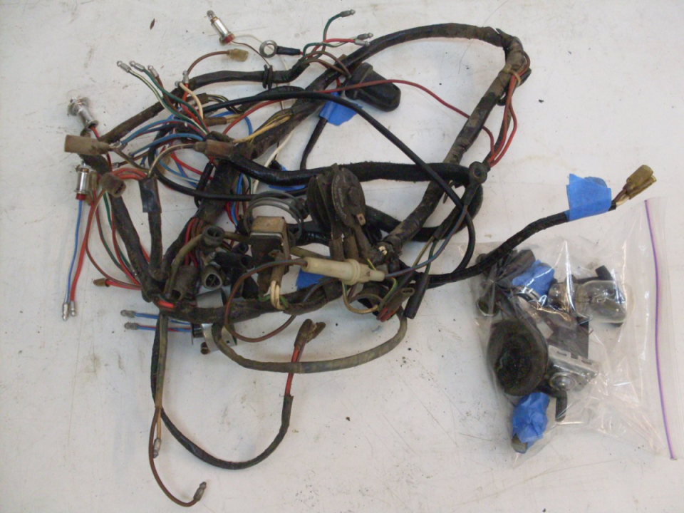
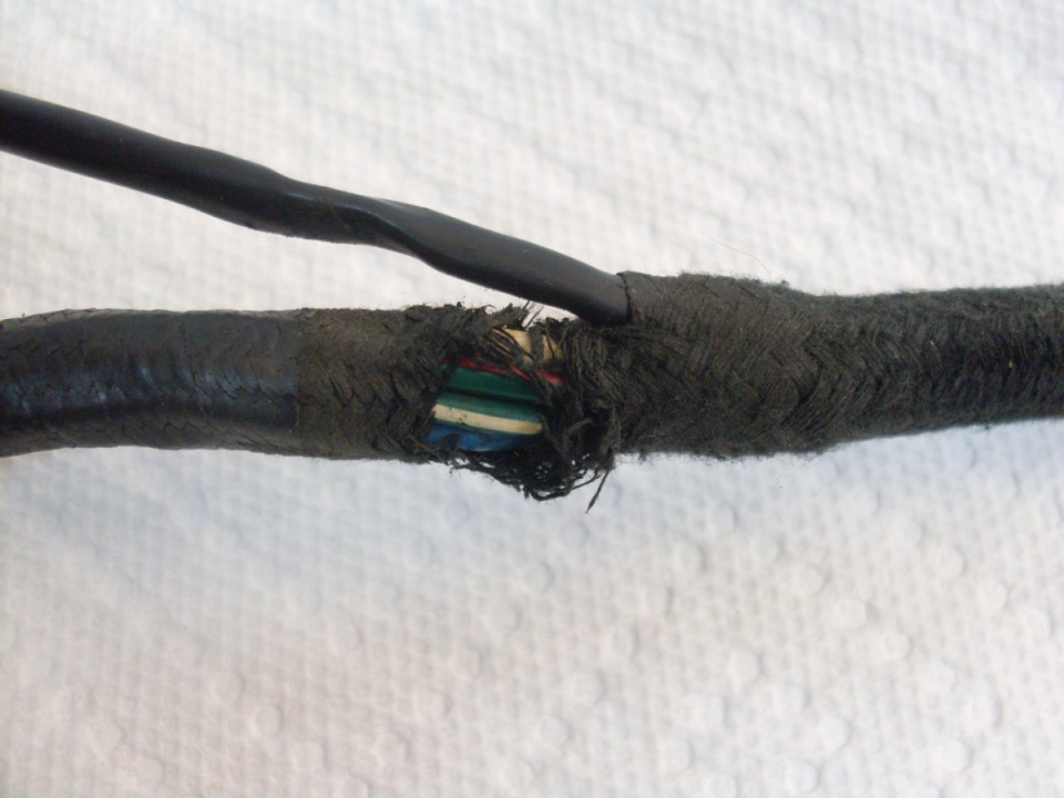
Besides the rotted loom and the mess with the tape, I found only a few other problems with the harnesses. One I knew about already.
This bike was stolen twice. Once in Schwabach, Germany, I was in a bar with some friends with the bike parked outside. I must not have had the steering locked, because when I came out it was gone. As I remember, the local Polizei didn't give me a lot of hope of retrieval, so I went looking for it myself. I found it about an hour later in back of another bar down the hill. I counted myself extremely lucky not to have to walk home that night. But I digress.
The second time the bike was purloined was a few years later back in the states. I was visiting a friend at his apartment, and when I came out, the bike was not in the parking stall where I left it. I looked around and saw someone on it coasting towards the parking lot exit. I hollared at him and took off in pursuit. When he saw me coming he panicked, and like the no-account weasel he undoubtedly was, he dropped the bike and ran. When I got to it, I found he had cut the wires to the ignition switch, stripped them, and twisted them together. I picked up the bike, kicked it, and it started right up. I was probably five seconds from losing it without a trace.
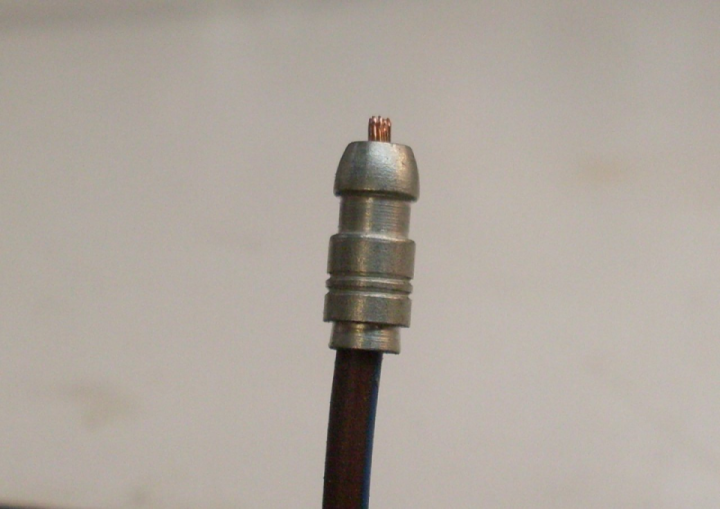
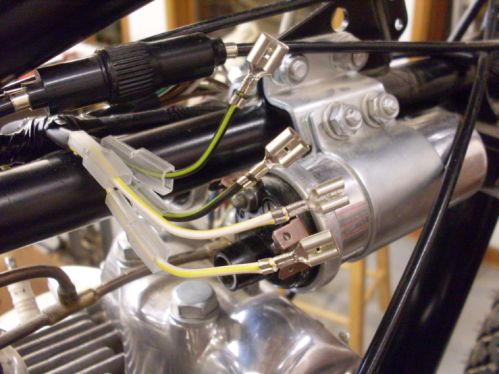
This is the story behind the abnormally short ignition switch leads. I later put spade connectors on what was left of the wires, but thet were way too short, and I couldn't fit the protective rubber boot over the switch.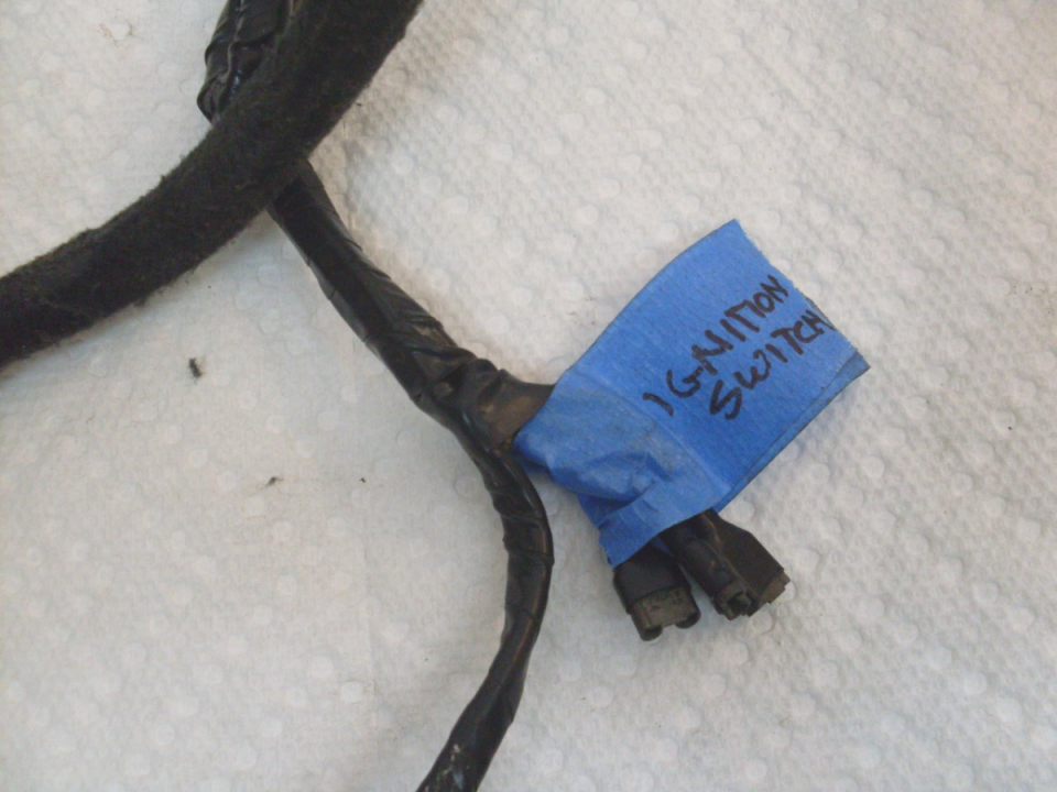
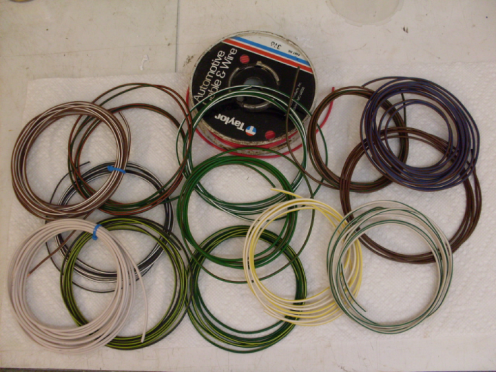
This is the front harness with all of the tape and rotted loom removed. Rather than try to splice in wire to replace the hacked off ignition switch leads, I decided to replace the wires in the harness. I also wanted to retain the correct wire colors, not so much for originality, but more to keep the harness colors consistent with the wiring diagrams. I thought future troubleshooters (including me) would appreciate it. There were a total of five wires to be replaced in three colors: white, brown with a white stripe, and brown with a blue stripe. All of the wires in the harness appear to be equivalent to what we in the US call 18 gage stranded. The British apparently prefer to call out the wire size by the number of strands (which is 14 in this case). Wire in original colors is available from a number of sources.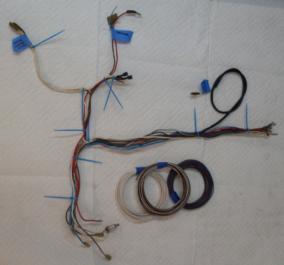
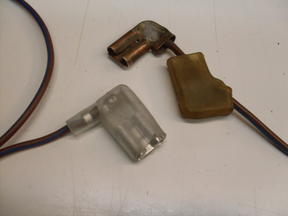
A couple of the wires to be replaced had common 1/4-inch female spade terminals on the other end. Triumph used plain copper terminals with the wire spot welded on, and a rubber protective boot. My replacement was a good quality tinned copper terminal soldered onto the wire, and the boot reused.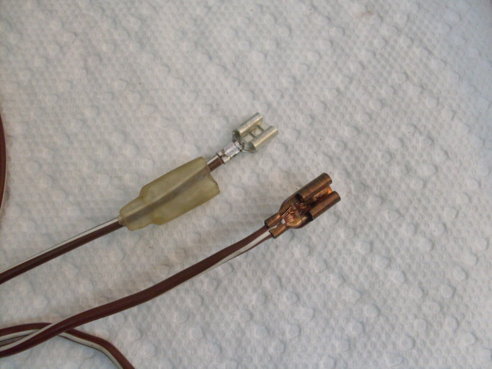
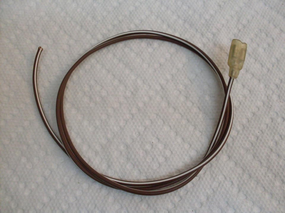
Another wire was the one to the large 3/8-inch spade connector on the Zener diode.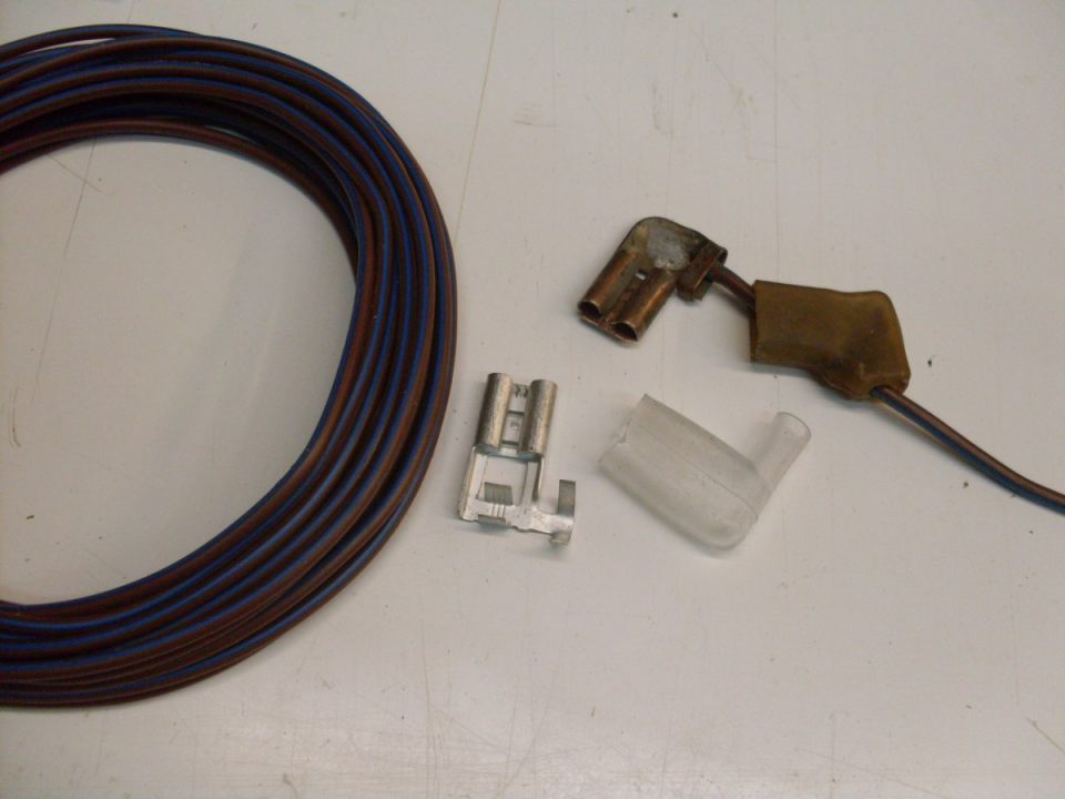
 Follow
1.4K


