Part 1 - Guide for replacing your regulator / rectifier
Introduction
Hopefully this will help people who decide to tackle the regulator/rectifier (RR) issues on their VFR.
This work is being carried out on a 2003 VFR 800 but the process should be pretty well identical for all the 800s.
There is a lot of information dotted around and some good videos from Kev’s Shed on youtube but I like having a piece of paper to refer to, hence this document. Over and under charging can both be attributed to failed/failing RRs, I’m going to work on the assumption that you know your RR is the problem, or you are just doing a preventative fix like I was.
Background
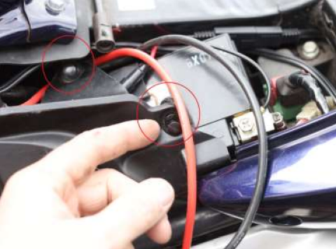
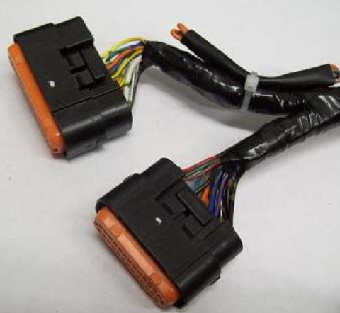
The regulator/rectifier (RR) takes three AC inputs from the stator (alternator) and combines them together to give a nice smooth book figure of 14.0 to 14.8 Volts DC at 5k RPM. The three input connections to the RR are three yellow wires that originate from the stator housing. These start at the stator windings, then head through a gland to a connector on the nearside front of the bike.
From here, we route over to the offside of the bike where another connector joins it to the RR. Each connection is a potential problem source with water ingress being a common issue. The wiring gauge (thickness or AWG for American Wire Gauge) is also quite thin so most people upgrade with a bigger wire or lower AWG.
The two other connections to the RR are a live feed (the charging to the battery) and a negative to complete the circuit. The standard RR have 2 positive and 2 negative wires which then join together. Again, the general recommendation is to replace this with new wire of a lower (bigger) AWG.
You can buy a specific harness to do this job but it’s really easy to make your own up and you can locate things exactly where you want then which is what I chose to do.
Which Regulator/Rectifier
So which RR do you buy? There are a variety of options out there and they all do the same thing i.e. take 3 stator wires in and produce a voltage out to the battery.
But … they aren’t really all the same. There are several ways of taking the messy AC (alternating current) signals and converting them into nice smooth DC (direct current) battery friendly values.
I recommend a regulator that has fast acting switches known as MOSFETs (Metal-Oxide Semiconductor Field-Effect Transistors). Examples are the Shindengen FH020AA (which I fit in this guide), or the SH847 (used on the VSTROM and Suzuki part number is 32800-31J00) which is a further improvement but both are an upgrade on the original part.
Sadly, not all MOSFETs (or FH020AA branded RRs) are equal. The quality of components and manufacturing vary greatly so you will find people with horror stories of cheap regulators failing in short order. The best bet is to buy one of the expensive genuine ones from a reputable source. Or just swap it out when the cheap one fails but be aware it could cause damage on the way out.
I bought a regulator with the connectors and mounting plate but these can be bought separately. The £20 eBay regulators come with the connectors if you’re feeling brave: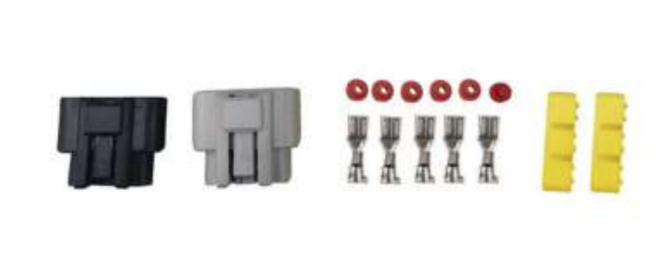
There are plenty of options here so don’t panic if you need to buy this separately
In terms of the mounting plate, I used 5mm thick aluminium which was 112mm x 95mm which is a good fit
Which Wire?
My view is that 12AWG is good for the three yellow wires to the stator and I chose 10AWG for the red/black to the battery/ground. 12AWG for both would have been fine and, at least on paper, you could easily make an argument for smaller wire than that. But my recommendation is 12AWG stator wires and 10AWG power and you will never have wire thickness to blame for issues.
The next decision is whether to use silicone or copper wires. I chose silicone because it’s really flexible and easy to router around the bike, and it has a nice 200 degree temperature tolerance which is great for us. You don’t have to, it will be perfectly possible to use standard copper wire if you wish, but there are clear advantages to silicone.
For the stator wiring, I bought: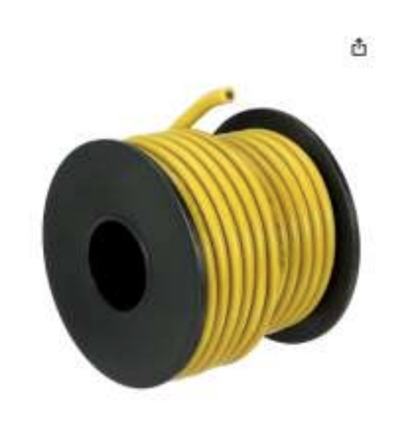
7.5 metres of 12AWG, yellow, silicone wire. £18.49
For the power wires, I chose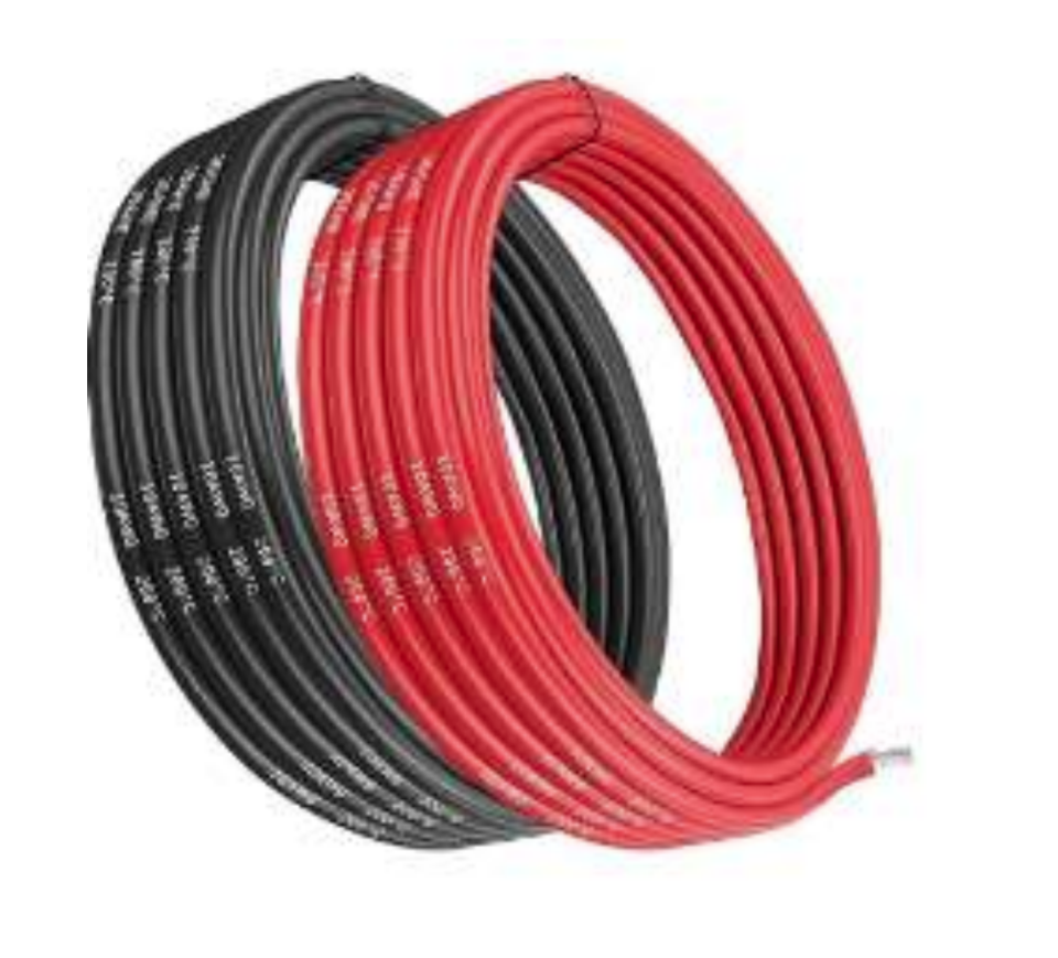
5 metres of 10AWG, red & black, silicone wire.
Fuses or Circuit Breakers
Below is the standard bike wiring diagram, you will see that the main power feed (R/W) from the RR to the battery goes through a 30 Amp fuse. This is important, without it, the power wire could short to anything and provide full battery power without any safety checks.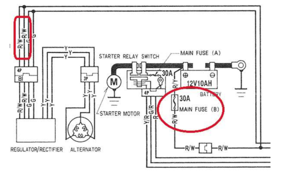
You can fit an inline blade fuse or, if you want to go for a fancy resettable option, a circuit breaker.
I felt fancy so chose this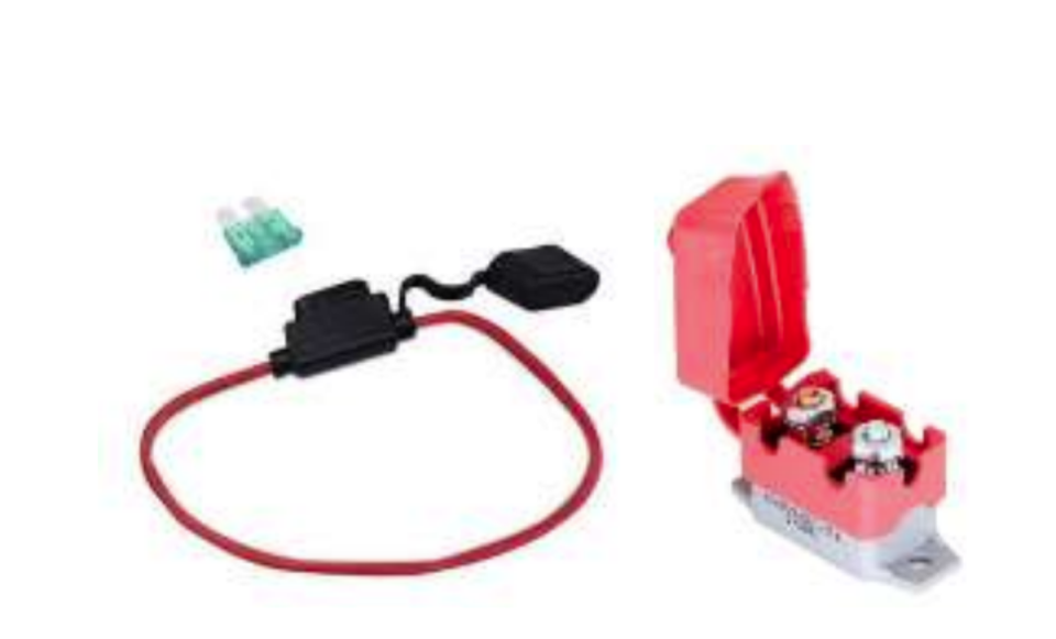
6-28V 30Amp circuit breaker, £6.99
Either option is absolutely fine, just make sure it is waterproof as moisture ingress is a common cause of issues.
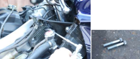
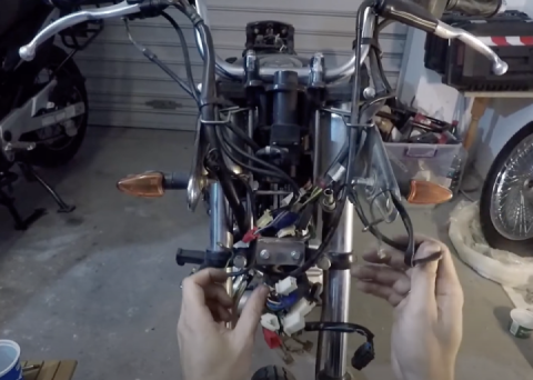
Preparing the Wiring Before we Disassemble the Bike
So we have a regulator/rectifier with connector and mounting plate, wire, a circuit breaker, and a strong desire not to have our bike set on fire. Now we get to work on the wiring before we get near the bike.
Start by sliding your seal onto the wire with the thinner end pointing to the end of the wire. Do this before you start thinking about crimping and realise you need to fit it first! With 12 AWG, the stock seals fit well and with 10 AWG they need a bit of encouragement but no need for cutting/modifying them.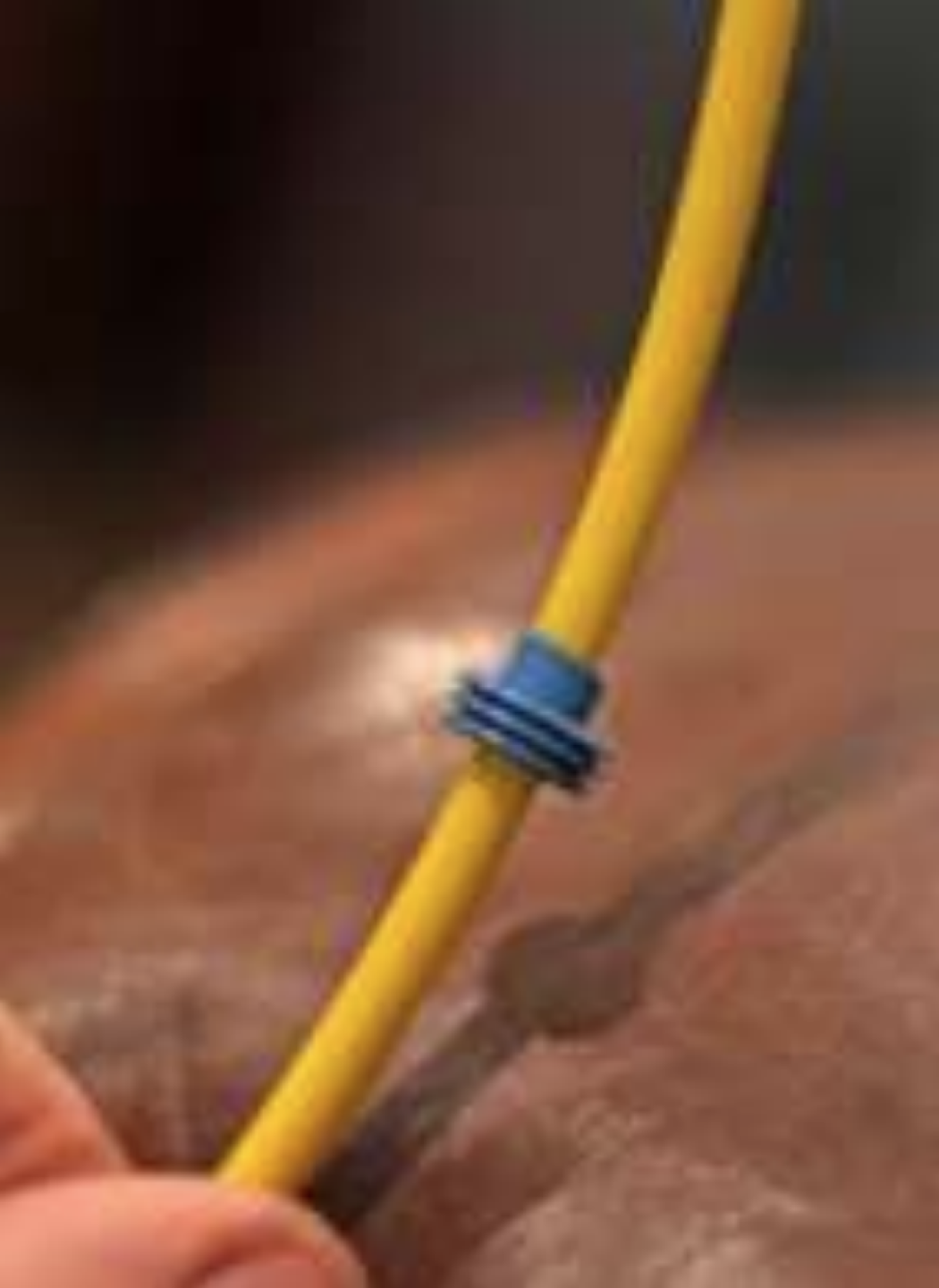
Strip approximately 7mm of insulation off the three pieces of yellow 12 AWG and the two 10AWG wires. I used a scalpel for this, just run it around with light pressure and it will peel away. Standard wire stripper tools can struggle with the flexibility of silicone so blades can be better (scissors can work fine too, just be careful not to cut too many of the wire strands as they are very thin). I ended up trying my wire cutters on it later on and they worked just fine though.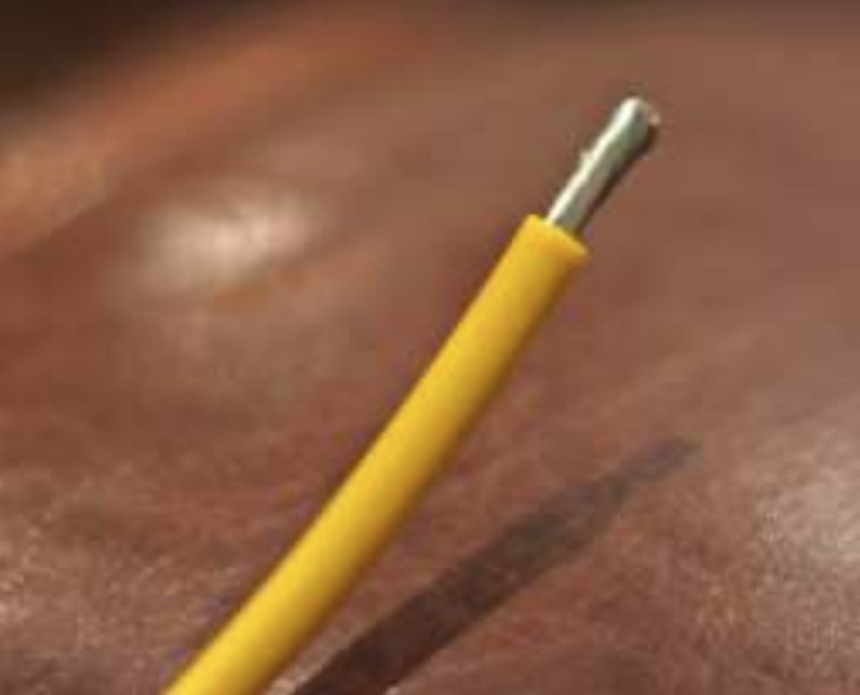
The length of wire you need will depend where you locate the RR, I kept mine all long until I got to the bike and would recommend you do the same.
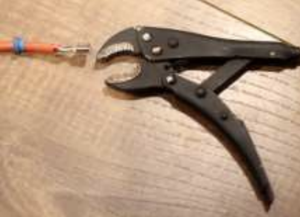
The crimps are a bit unusual in that they are quite large. I have a range of crimp tools and none were suitable so I had to go down the pliers route. I was not keen to do this but it actually ended up fine so don’t worry if you need to do the same.
Slide your neatly stripped wire end into place. The insulation should be aligned with the bottom clamp and the bare wire sitting snugly in the channel at the top for the second set of arms to fold as shown below: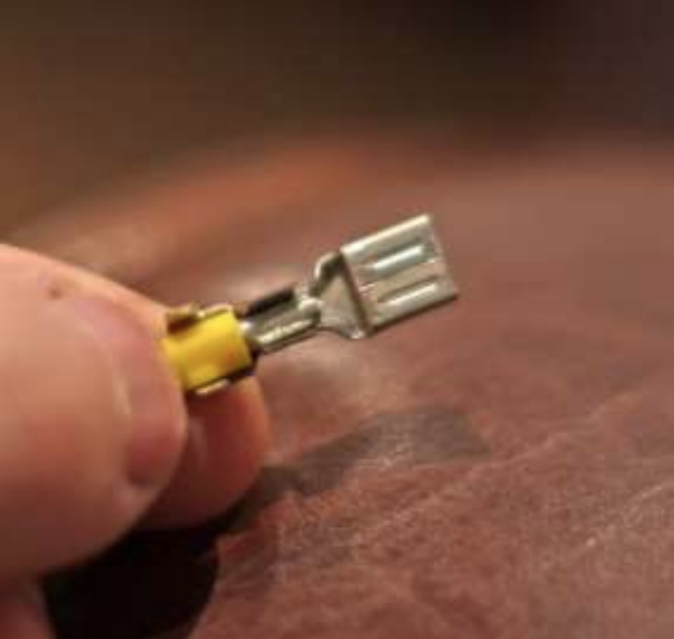
I used pliers to fold in the tabs to start things off and then some small mole grips to make the crimp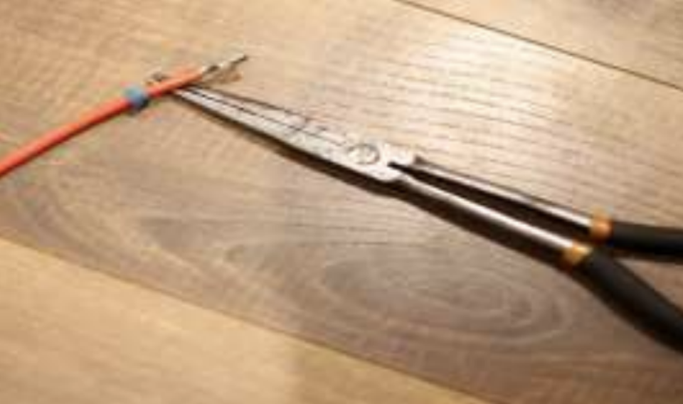
Whilst the end result isn’t as good as a crimp tool, it’s more than adequate. Pliers again to grab the insulation.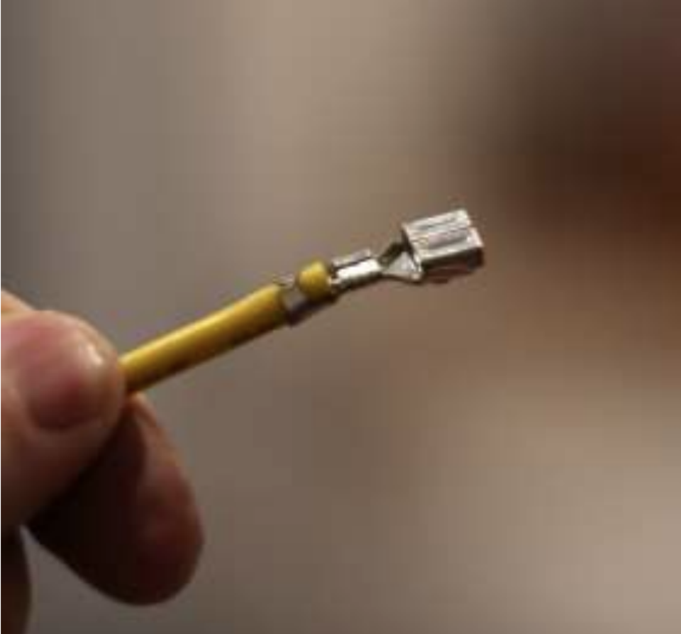
Repeat this 5 times and you will be ready for the next step.
Solder or No Solder? A proper crimp is perfectly adequate and used all over vehicles where solder is not. It’s easy to get reproducible good connections with crimping. Soldering, when done properly, not. It’s easy to get reproducible good connections with crimping. Soldering, when done properly, can make a good joint too. I think you’ll end up with a bit of a mess and no real mechanical or electrical improvement by adding solder so chose to just crimp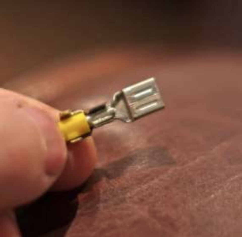
Once you have crimped the wires (and soldered if you choose), simply slide into the connector and hear a satisfying click as it locks into place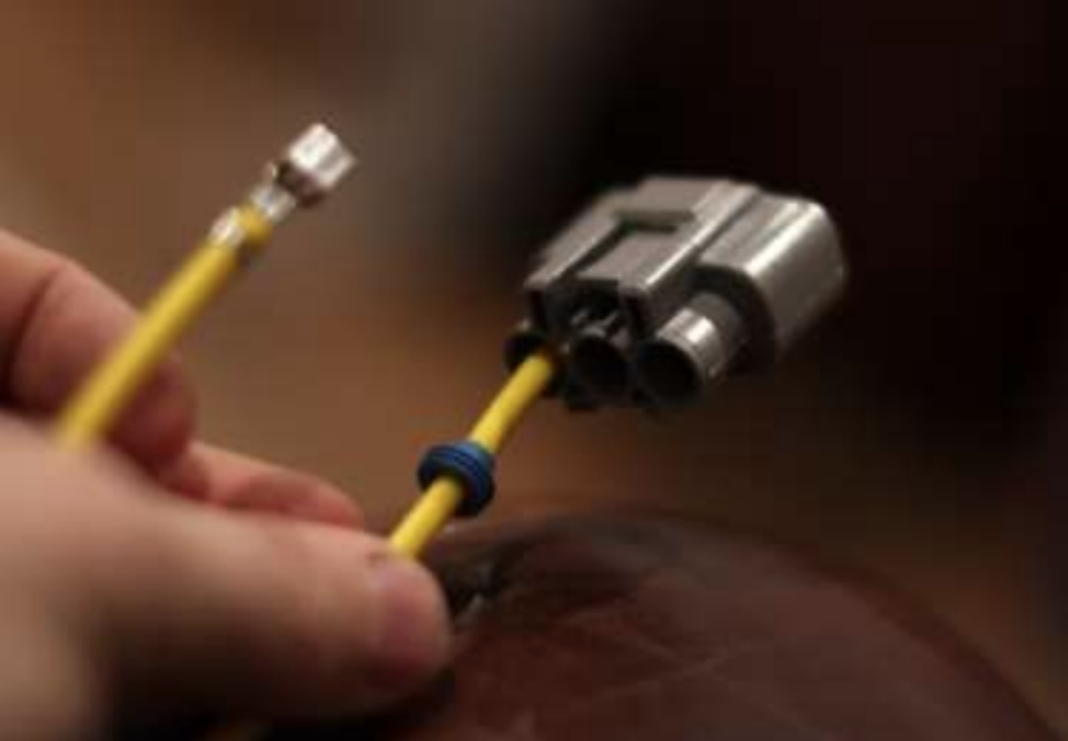
Orientate the folded metal tabs with the slot in the connector as shown, don’t put it in upside down or it won’t click in. You might want a small flat blade screwdriver to seat the terminal if tight.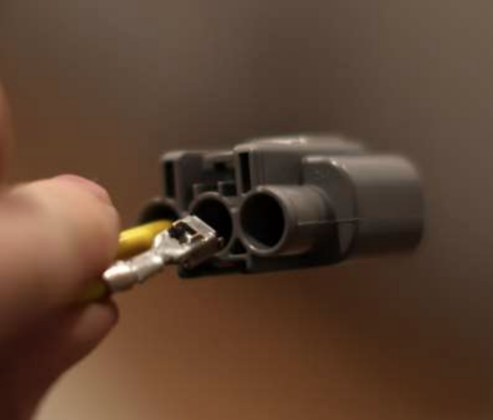
The next job is to make it water tight, simply slide the cable glands up into the connector and ensure each rib is worked fully into place leaving a flush finish. Again, you might find some careful easing with a flat blade screwdriver helps you tuck this into place, especially on the 10AWG wire but no stabbing! Lever into place in a sideways movement rather than push.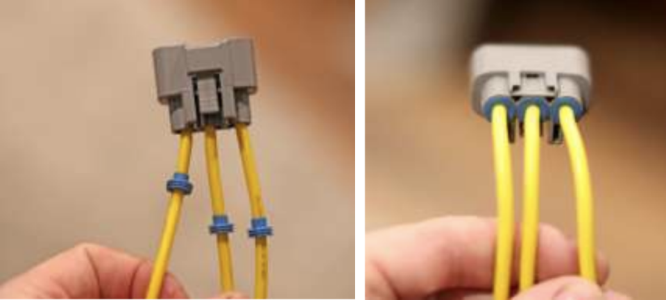
Once the stator wires are done, move onto the power wires in the same way. The only exception is that you should have a blanking bung in the middle pin of the connector as we only use two wires (don’t leave a hole or water can track in)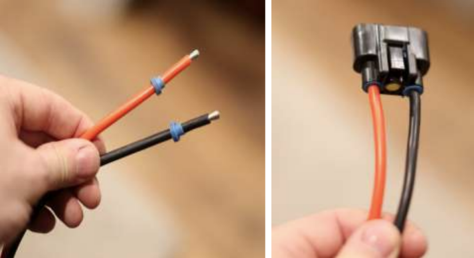
Test fit the connectors in the RR and you have a half wired loom ready to go to the bike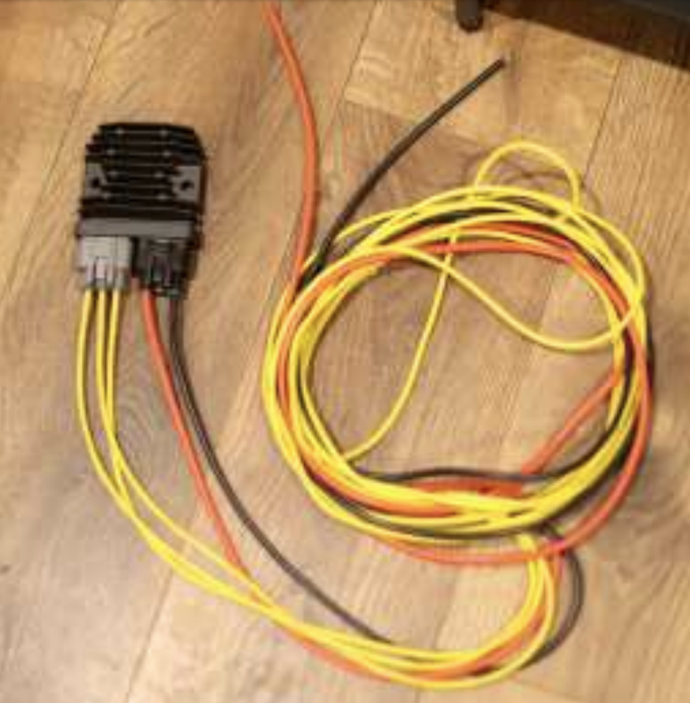
 Follow
4.3K
Follow
4.3K