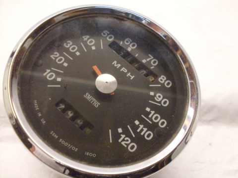
Instruments Pt. 2
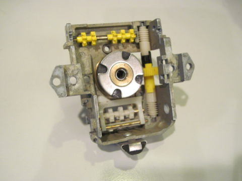
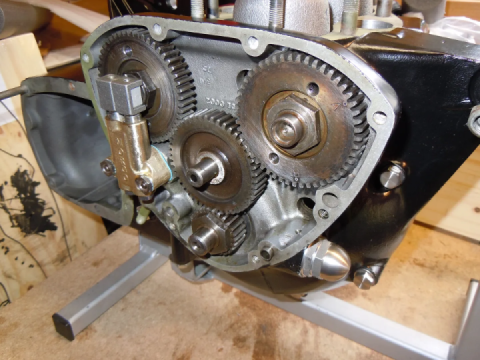
After the pointer needle (what was left of it) was pried off, the dial came off by drifting out the center keepers of the two small reusable plastic rivets. This reveals the internal mechanism. All magnetic speedometers and odometers I've had apart employ the same basic principles, and here's a synopsis of how it works (see annotated pic below): The speedometer (or tach) cable connects to the bottom of the casting, and the cable's inner flexible shaft turns the input spindle of the instrument, which has both the brass worm gear and the dark grey magnet pressed onto it, so the gear and the magnet both spin at the same speed as the speedometer cable core. The worm gear drives the odometers through a chain of plastic gears. Just above the magnet, but not touching it, is an aluminum disc. The disc is on a smaller spindle that extends up through a hole in the brass spindle plate, and down into a recess in the center of the magnet. The hole in the spindle plate and the recess in the center of the magnet serve to locate the spindle so that the disc is always parallel to, but not touching, the magnet. The upper part of the disc spindle has a collar pressed onto it above the spindle plate such that the disc and spindle are hanging from the plate, supported by the collar. The collar also holds one end of a spiral return spring so that when the disc turns, it winds the spring.
Now, even though aluminum is not magnetic, it is conductive, so when the nearby magnet is spinning, electric currents start to flow in the aluminum disc. These currents create their own mangnetic field which reacts with the field of the magnet such that the disc tries to spin with the magnet. The torque created by the disk trying to follow the magnet is opposed by the spring. Since the torque on the disc goes up as the magnet spins faster, the result is that the disc rotates against the spring in proportion to how fast the magnet is spinning. The indicator needle is attached to the spindle, so the needle shows how far the disc rotates.
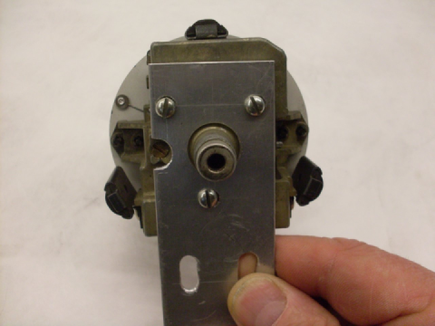
The steel modulator plate is provided as part of the magnetic circuit so that the strength of the magnetic field that the disc sees from the magnet can be varied. If the modulator plate is moved closer to the disc, the field is stronger, and the torque for a given magnet speed is increased, Adjusting the modulator plate is how the speedometer (or tach) is calibrated. There is a screw accessible on the back of the main casting that moves the modulator plate against the spring that can be seen to the right of the magnet. 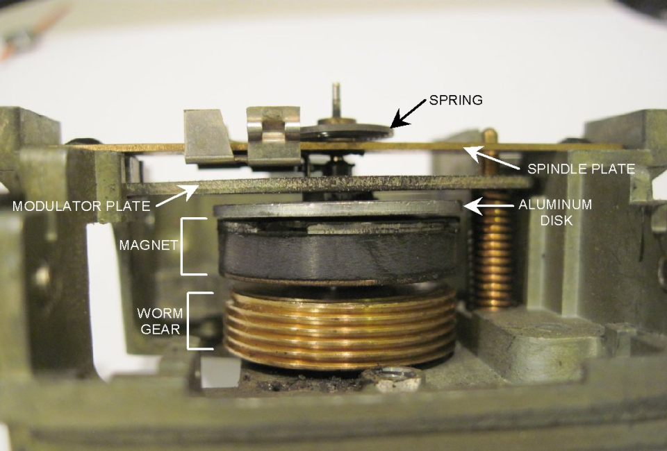
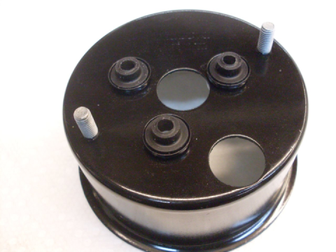
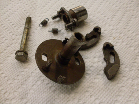
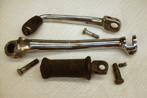
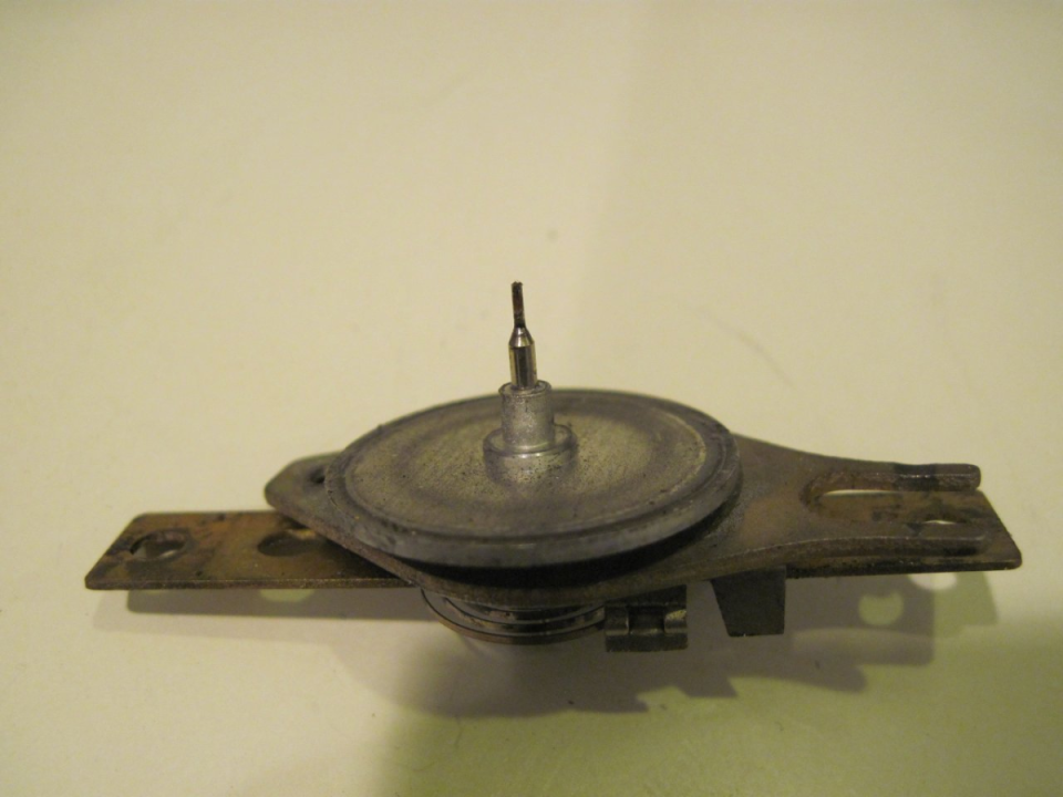
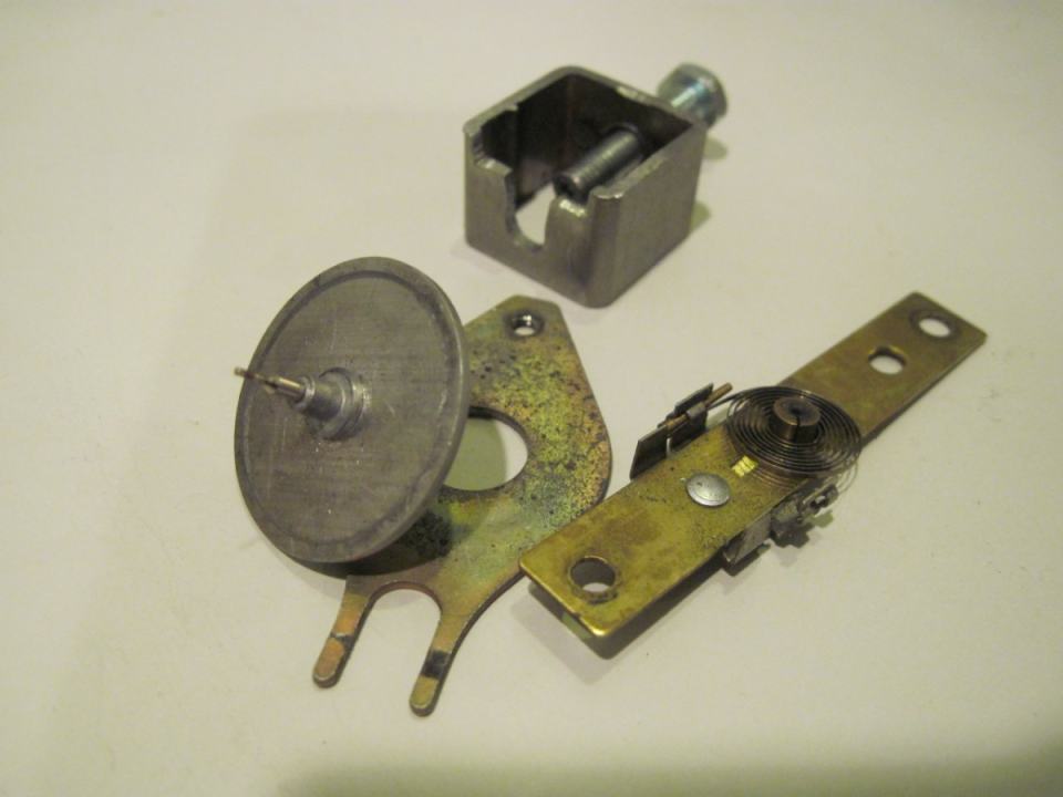
Here are some other views of the disc assembly (disc and spindle, modulator plate, spindle plate, collar and spring) removed. The assembly is held to the casting by more of those reusable plastic rivets.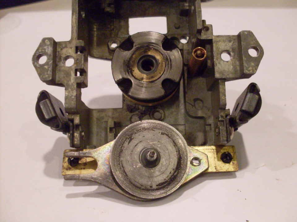
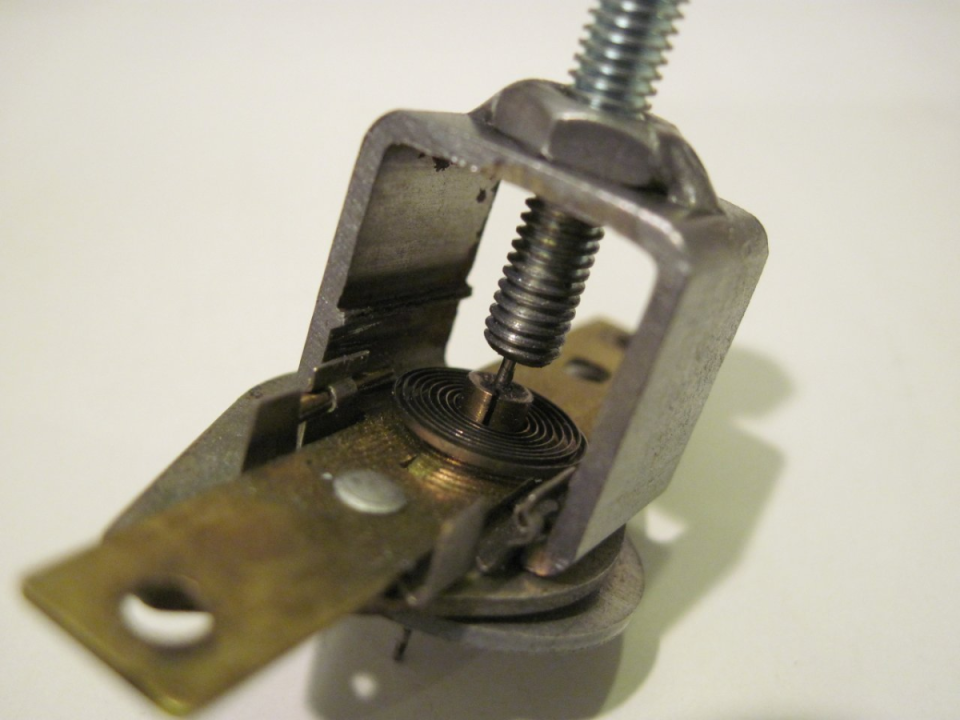
In order to inspect for wear, the disc assembly has to be taken apart. This is done by pulling off the pressed on collar from the disc's spindle. Shown is a collar removal tool like those used by RC model car hobbyists. It inserts under spindle plate, and the screw pushes the spindle through the collar.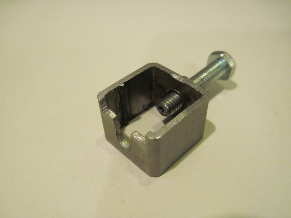
One thing I nearly lost was a tiny washer under the spring collar on both instruments. In effect, this is a thrust bearing that takes the weight of the disc and spindle while minimizing contact area. 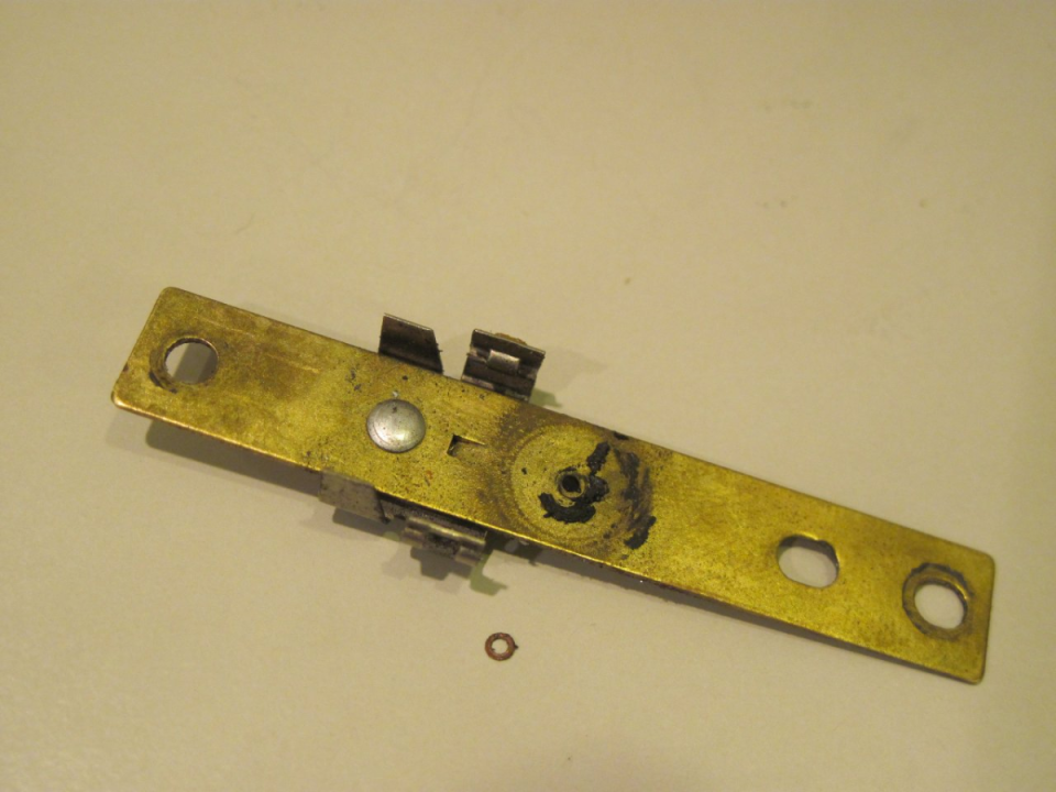
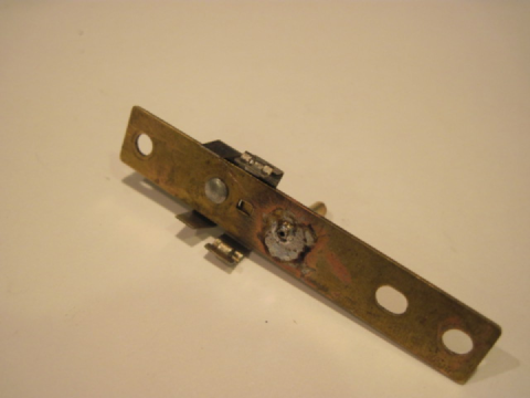
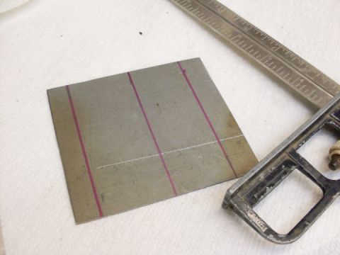
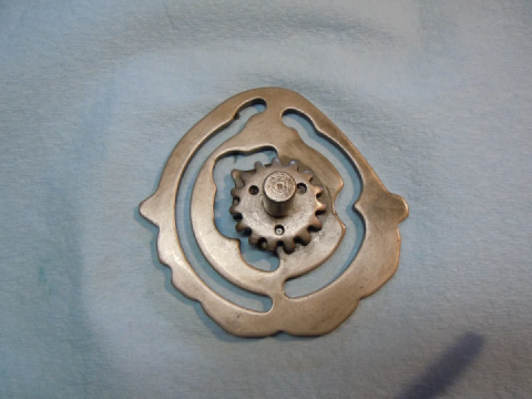
Here is one thing I found that explains a lot. These are the spindle plates from the two instruments. The hole near the center of the plate is the locating hole for the disc spindle. The spindle where it passes through the hole is slightly less than one mm in diameter, and the hole diameter should therefore presumably be about one mm. The hole in the bar to the rear is very slightly oversized, but the one on the front is a little over 2 mm! It was pretty obvious that this needed to be fixed.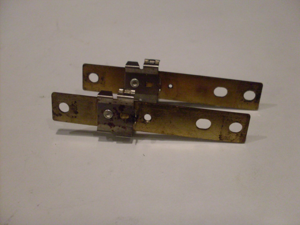
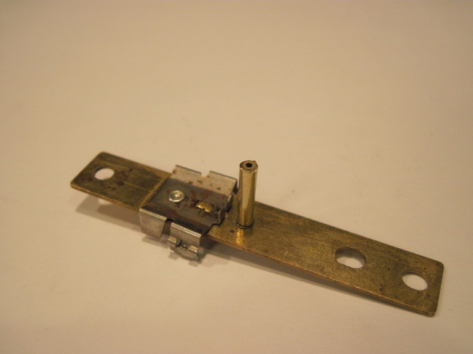
I fixed the problem by using some small telecoping brass tubing from a hobby store. The larger tube measures 0.093 OD, which was very slightly larger than the hogged out hole in the spindle plate. A #42 drill is 0.0935, and it made a nice fit for the tubing. Luckily, the enlarged hole was still centered in the plate, so drilling was simple.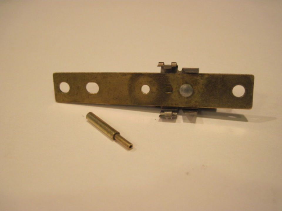
 Follow
1.3K
Follow
1.3K