Instruments Pt. 5
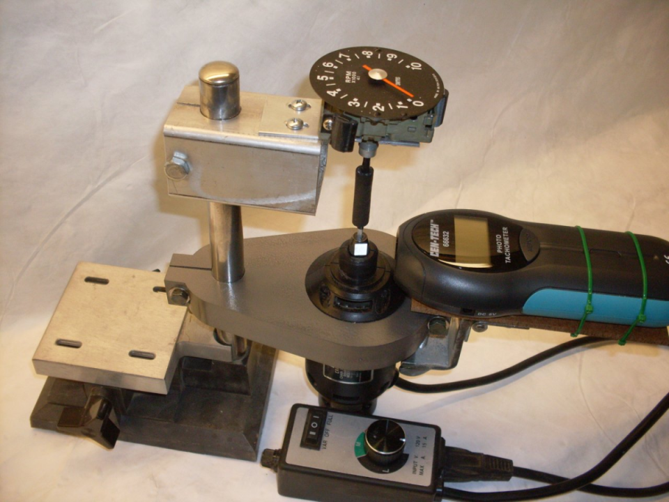
Put the faces and pointers back on , and now it's time to calibrate. I built a jig to hold the instrument, a variable speed drive motor, and an optical tachometer. The stand is from a little Dremel drill press. At first I tried to use the Dremel tool as a motor to spin the instruments, but after I got everything made and set up, I found the Dremel turns counterclockwise. I took it apart to see if I could remedy that. It was a permanent magnet motor, and while they are easy to reverse in principle, this one was so tight inside, there wasn't a good way to do it. Next try was a Craftsman chainsaw sharpener. It too ran counterclockwise, but was a series wound universal motor, so all I had to do was reverse the brush wires. The shaft from the motor to the instrument is 1/8" key stock turned to 1/8" round to fit the motor's collet. I ended up cutting the shaft in half and joining it with a piece of rubber tubing to accommodate a little misalignment better. I used an electronic motor speed control to vary the speed.
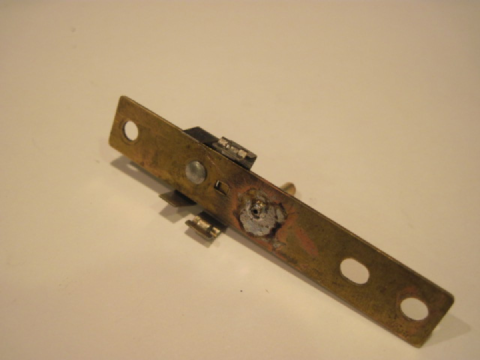
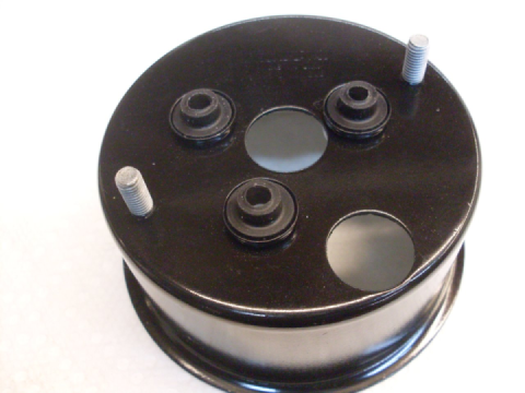
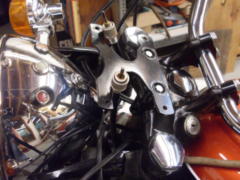
First picture shows the adaptor to mount the instrument on using the three threaded holes in the back ofthe casting. What looks like maybe 8-32 threads are really 4BA, which is 0.142 x 38.5 tpi. The calibration screw is also visible. 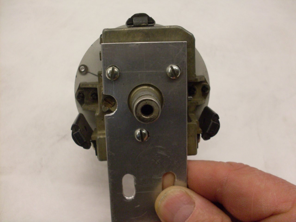
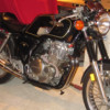
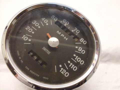
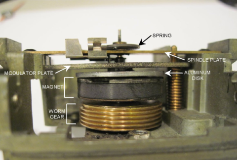
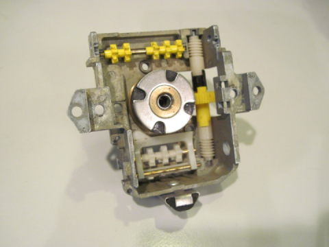
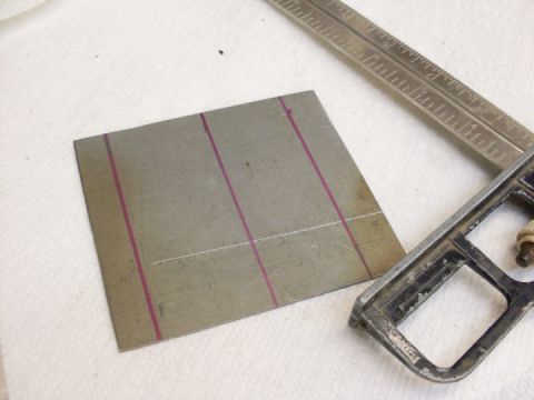
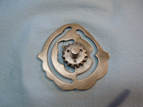
The tach is a 4:1 instrument (as indicated on the face shown in the second picture at top), so 1000 rpm on the input shaft should read 4000 rpm on the tach dial. Turning the calibration screw on the back of the unit moves the modulation plate, varying the magnetic field the aluminum disk sees. Smiths speedometers like this have a marking on the bottom of the face that indicates the number of revolutions of the cable that will rack up one mile on the odometer. On mine, it was 1600 (see very first picture above). This implies that 1600 rpm on the input cable should indicate 60 mph (one mile per minute). Both instruments calibrated fine, and appeared to be working well.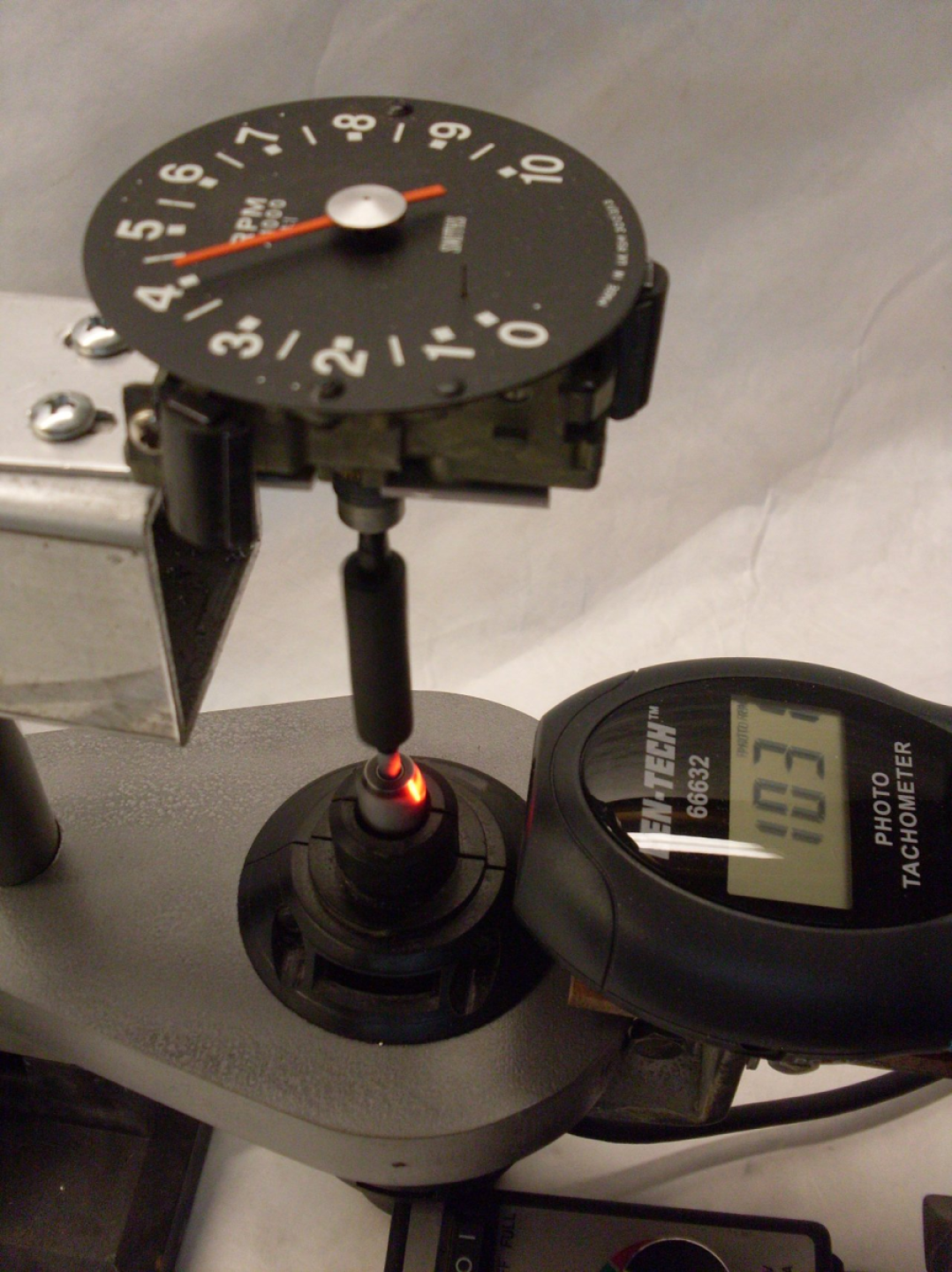
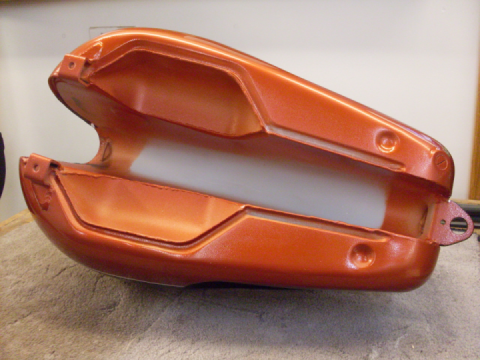
So with the guts in servicable order, I turned to the "cans", or shells that the instruments mount in. They were in good shape, but the paint and the rubber parts had seen better days.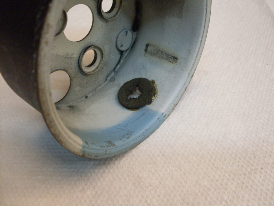
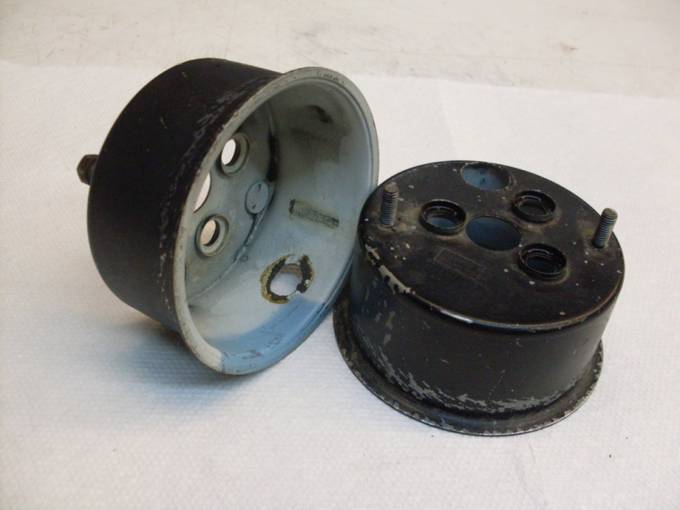
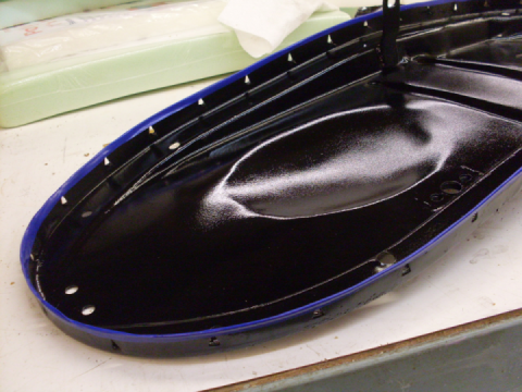
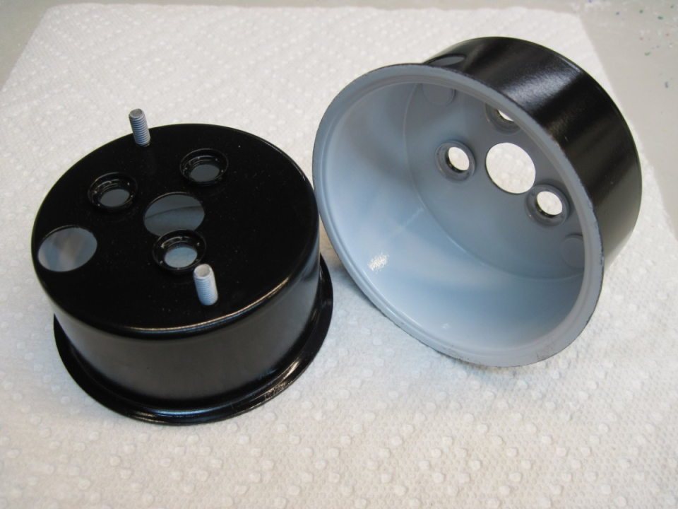
The cans cleaned up well with a little blasting and paint. The inside is painted white so that more of the light from the internal instrument light makes it to the dial face. There was a greyish area painted on the originals, which I assume is to mute the light right above the lamp, so as to even out the light on the face. It hadn't been applied yet in these pics.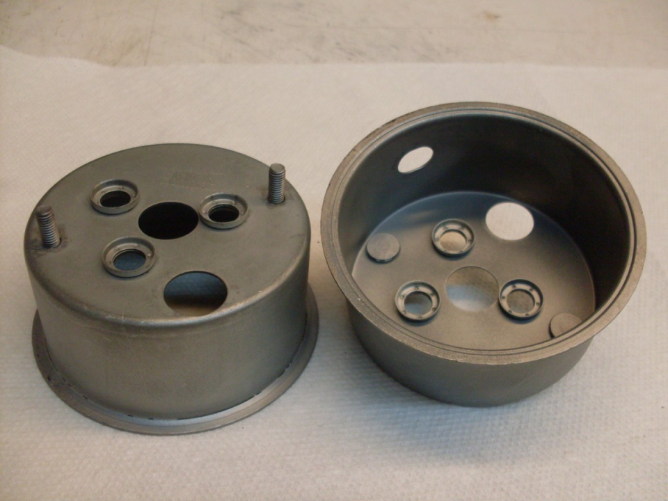
The rubber parts weren't so easy. There are six grommets in each instrument that serve to isolate the internal mechanism from vibration or shock. These were all badly distorted and deteriorated. There was also a rubber disk with a slit to seal around the trip odometer reset shaft.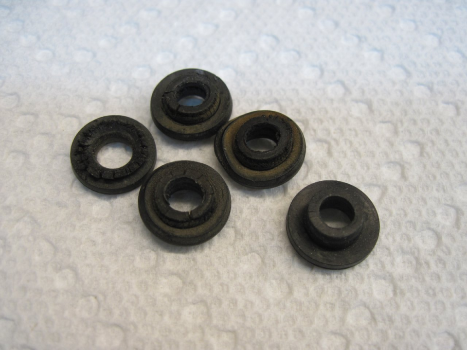
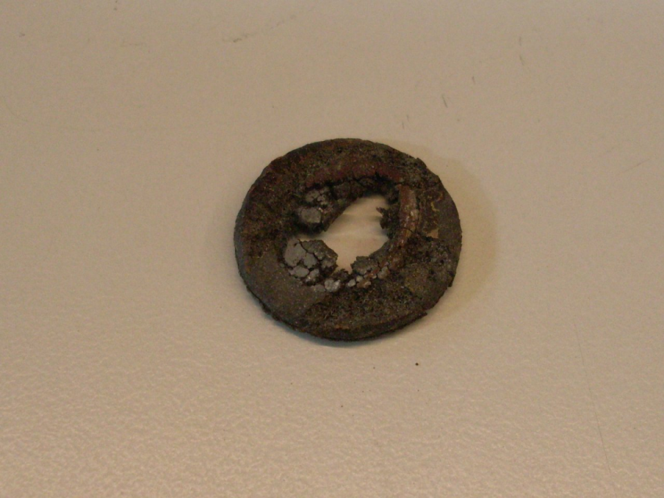
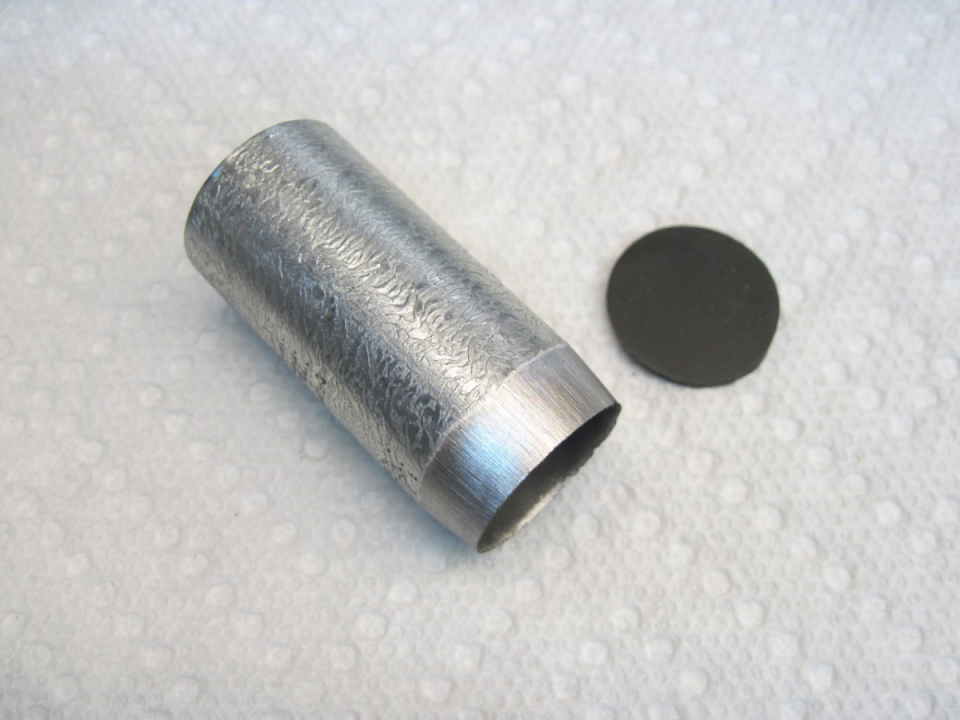
I found a place claiming to sell grommet/hardware kits, but they didn't really have them available. The fallback position was to make new ones, but since that process was fairly involved and not pertinent to this story, I'll skip over it here. Here are the new grommets, and a new little gasket for the trip odometer reset tool. It was punched out of some rubber sheet with that one-use punch made from a piece of sharpened electrical conduit: 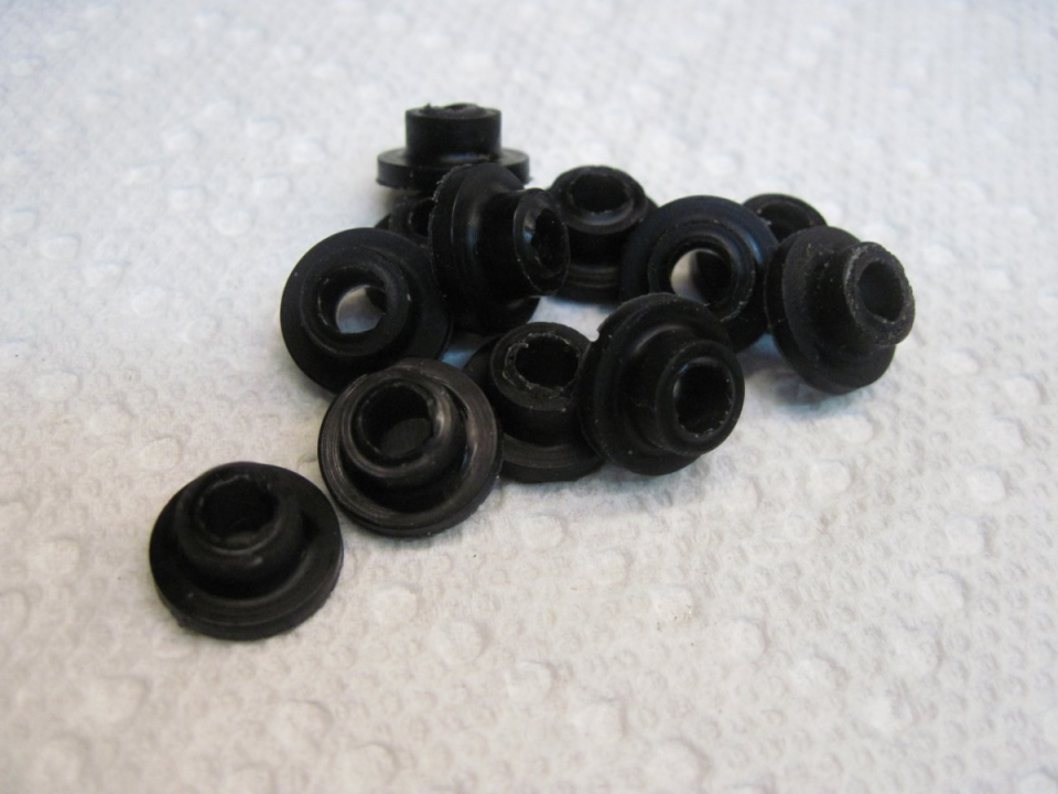
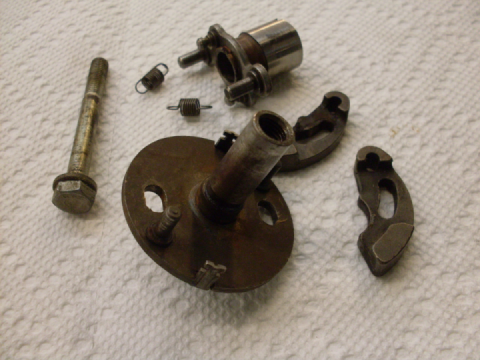
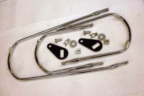
The replated the special mounting hardware. Those screws are 4BA threads. Not much chance of finding those at Home Depot.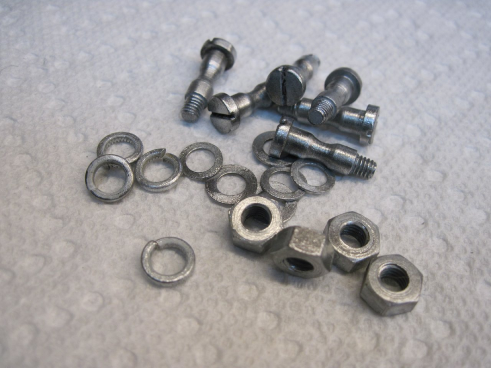
Everything ready to go together.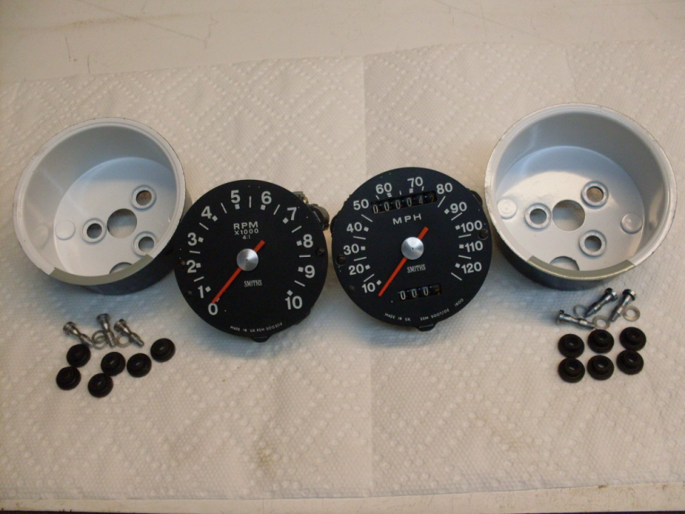
 Follow
1.3K
Follow
1.3K