Part 4 - Guide for replacing your regulator / rectifier
Wiring the RR
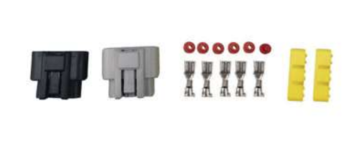
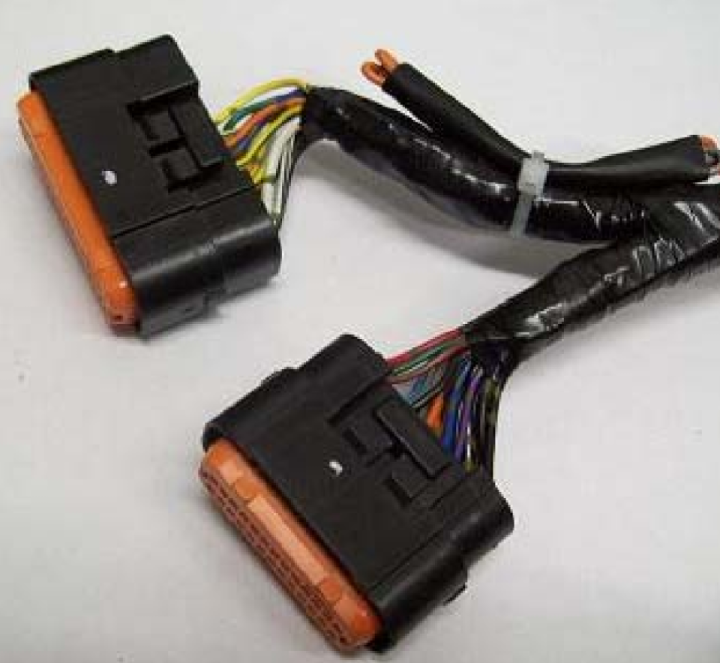
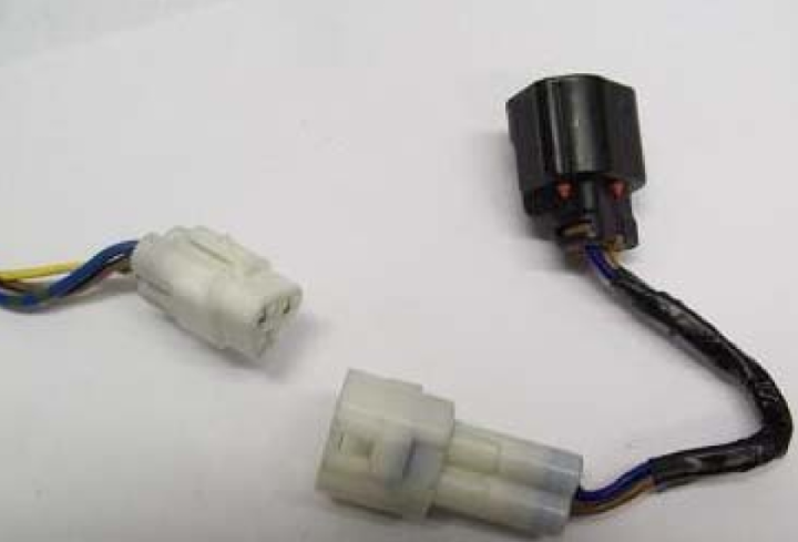
We earlier prepared a nice long loom to go on the bike, now it is time to fit it. Plug the two multiplugs onto the RR. Note I left the stock plugs in place, I have no intention of using them but they are a nice backup for the working RR I had in case of emergencies. You can remove/block these off if desired. Note I had a black/white wire in my plug to the regulator’s power side, this is on some models but not others and is just a switched live, you don’t need to do anything about it.
A bit of tape to hold our wires together and feed it through the bike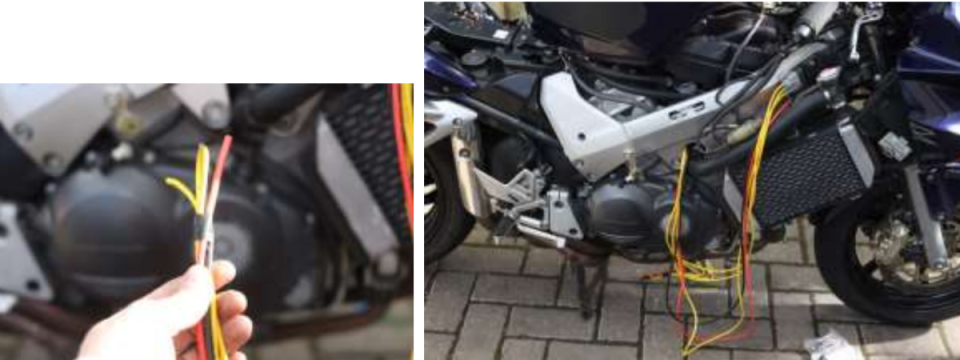
The help of a friend/wife here can be useful here, and a torch, and a long screwdriver to help guide it through the various potential snags.
Once you break through, you can loom up/cable tie/insulate the wires that will cross the bike. 70cm should be just right to pop out the other side all taped up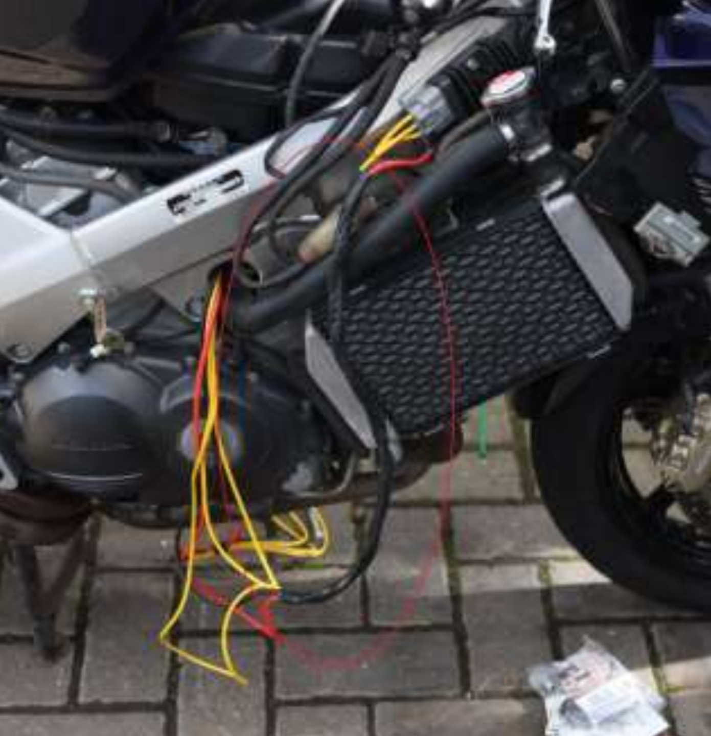
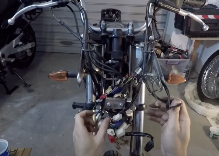
All piped in nicely: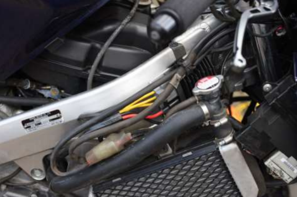
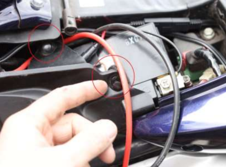
Now we move to the stator side where you should have 5 perfectly loomed wires waiting for you: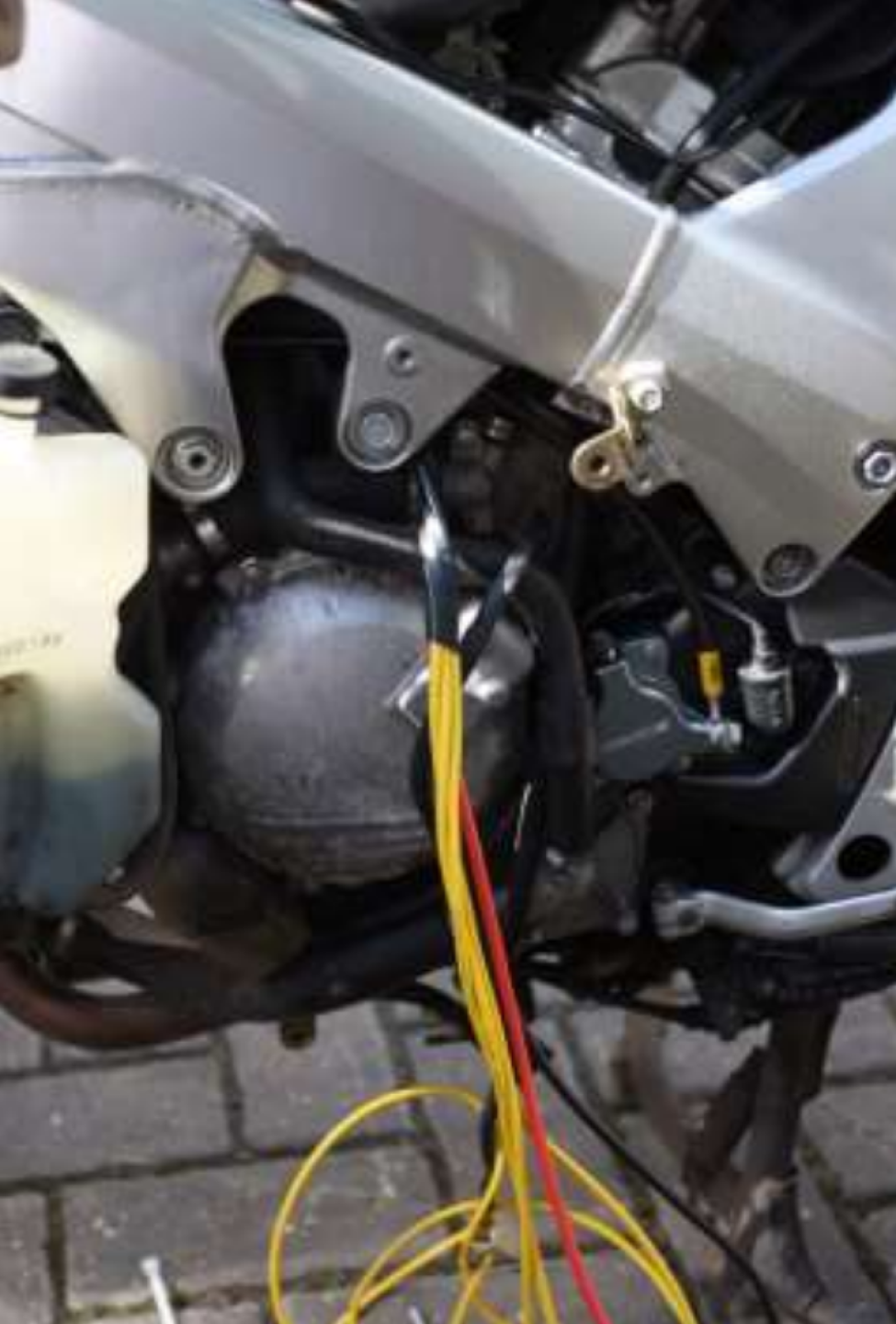
I fed the power wires up and out of the way so I could focus on the stator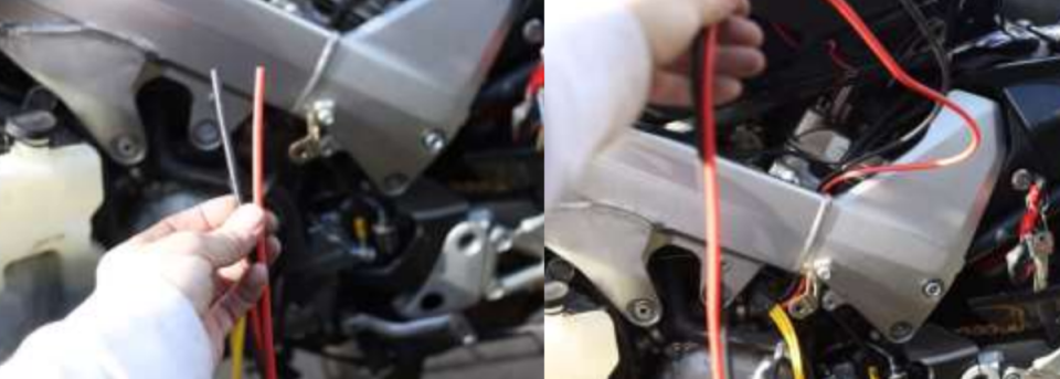
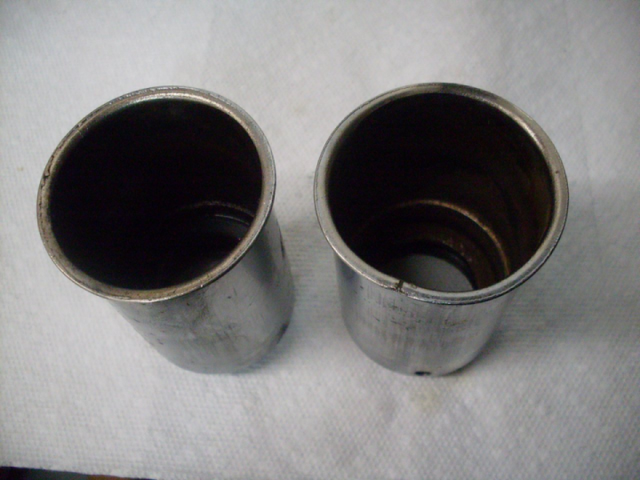
The time has come to cut the stator connector off. I left about 4-5 inches of spare wire on so there was plenty to play with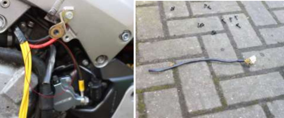
Slide off the old heatshrink (you can trim this and re-use if you need to, I didn’t use it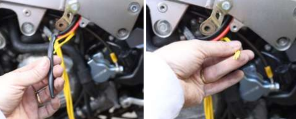
Have a good look at your stock wires, mine were actually in great shape, supporting my decision not to whip the stator out this time
Despite my earlier comments, I tried using my wire strippers on some spare silicone wire and they worked perfectly, so away I went stripping a good 1-2 inches off each of my new wires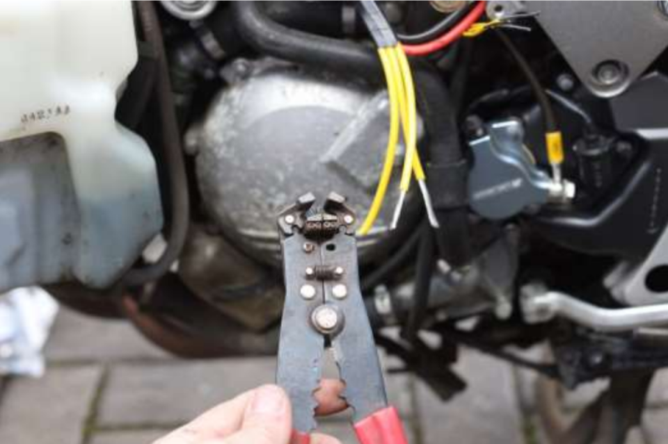
If you’re using heatshrink then don’t forget to slide it on before you solder. Insulation tape can be used instead. I did both (solder is spikey and heatshrink gets stabbed and can be brittle after being heated so I like to use both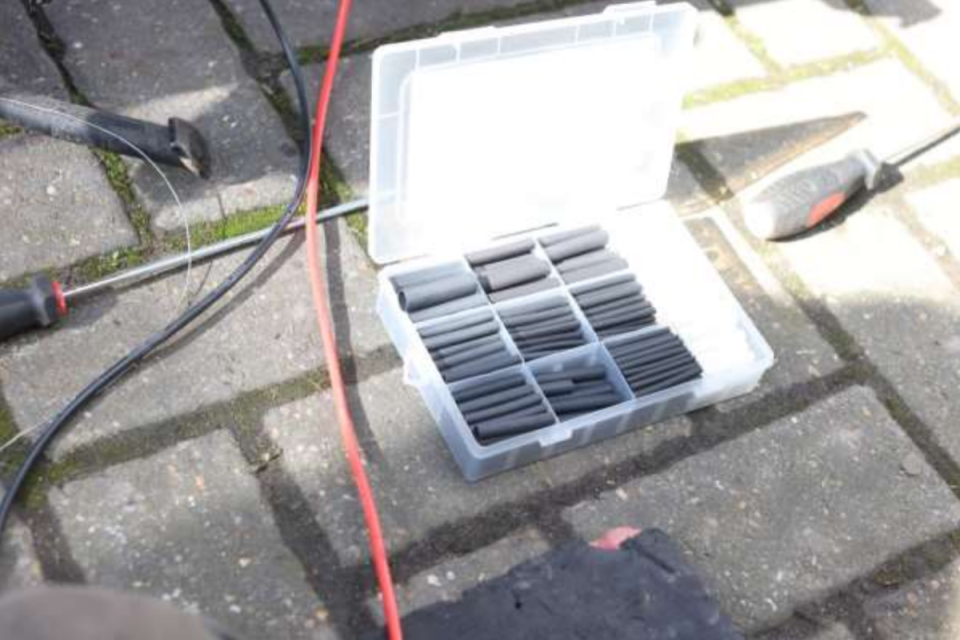
Tin each wire and then slide the heatshrink on. If you’re not a keen solderer then my top tip for you is that you’re heating the wire not the solder. Solder has a deliberately low melting point, your job is to get enough heat in the wire that it will suck in that lovely tin mess and make a good joint. So bad a little solder on the iron tip and press it against the wire then feed solder into the joint. If it doesn’t glide in then hold back, heat the wire for another 5 seconds with the iron then try again. You’ll know when you get it right because it will just gobble up your solder.
It makes no difference which yellow wire joins from the old loom to the new loom, they are completely interchangeable.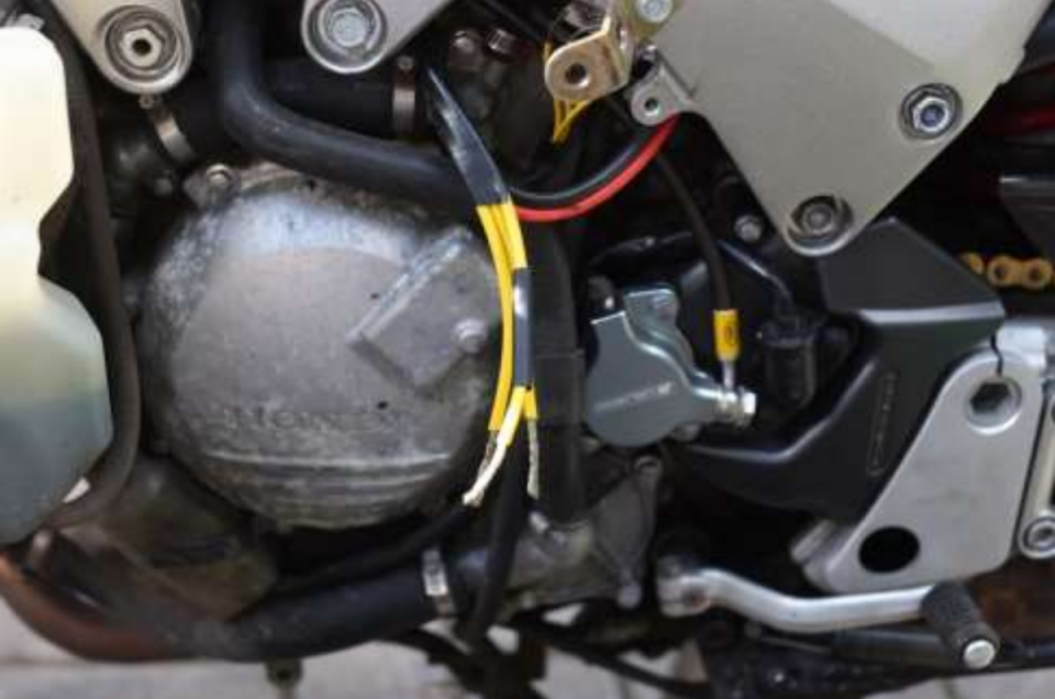
Once each wire is tinned, you can strip back the stock wires leaving an enormous 2-3 inches of bare wire exposed. You can then press the wires together and wind the long stock wire around our nicely tinned new wires as shown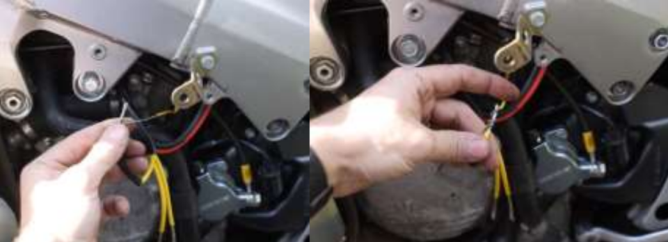
Now get soldering again, remember we’re heating both the wires as much as we can. The tinned wire will start to melt and then you can feed in solder to the old bared wire to make a joint like this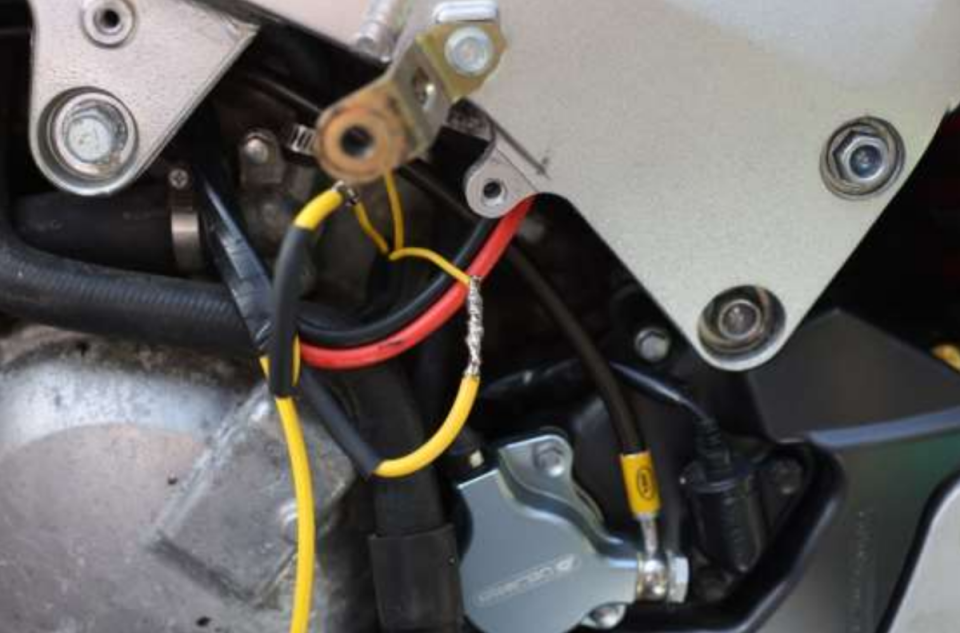
I popped a piece of tube I had lying around behind the wires before heating the heatshrink so nothing behind got too warm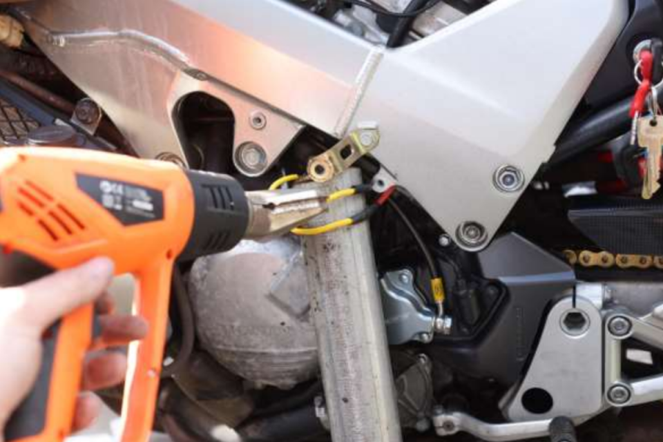
Tape each joint and then loom the three together with insulation tape and fit in place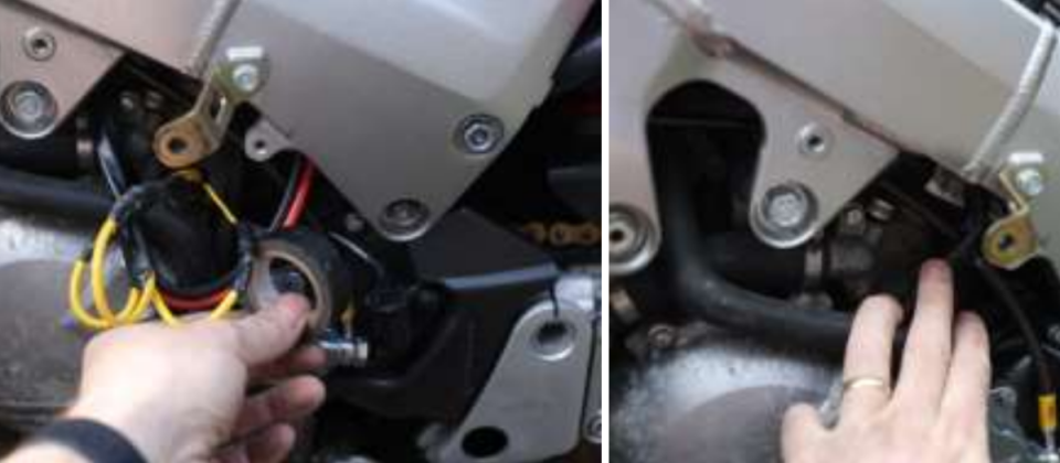

 Follow
928
Follow
928